Optical fibre connector face geometrical parameter measuring instruments

A fiber optic connector and geometric parameter technology, which is applied in the field of optical fiber connector end face geometric parameter measuring instrument, can solve the problem of difficult to ensure the eccentricity of the vertex of the spherical surface, the measurement accuracy of the height of the optical fiber and the inclination angle of the end face, the difficulty of accurately determining the center of the optical fiber, and low precision, etc. problem, to achieve the effect of avoiding the transmission of errors, ensuring robustness, and improving measurement accuracy

Inactive Publication Date: 2006-09-27
SHANGHAI INST OF OPTICS & FINE MECHANICS CHINESE ACAD OF SCI
View PDF0 Cites 1 Cited by
  • Summary
  • Abstract
  • Description
  • Claims
  • Application Information

AI Technical Summary

Problems solved by technology

Since the two rarely form step-like mutations, it is difficult to distinguish the relative position of the optical fiber and the ferrule body from the three-dimensional shape data of the end face, and it is difficult to accurately determine the position of the center of the optical fiber, so it is difficult to ensure the eccentricity of the vertex of the spherical surface and the height of the optical fiber. and the measurement accuracy of the inclination angle of the end face
[0007] (2) This technology uses Newton rings to measure the radius of curvature of the end face, which must be manually interpreted by the Newton ring fringe series, the accuracy is not high, and manual intervention is required, it is not suitable for instrumented automatic measurement

Method used


Image

  • Optical fibre connector face geometrical parameter measuring instruments
  • Optical fibre connector face geometrical parameter measuring instruments
  • Optical fibre connector face geometrical parameter measuring instruments

Examples


Embodiment Construction

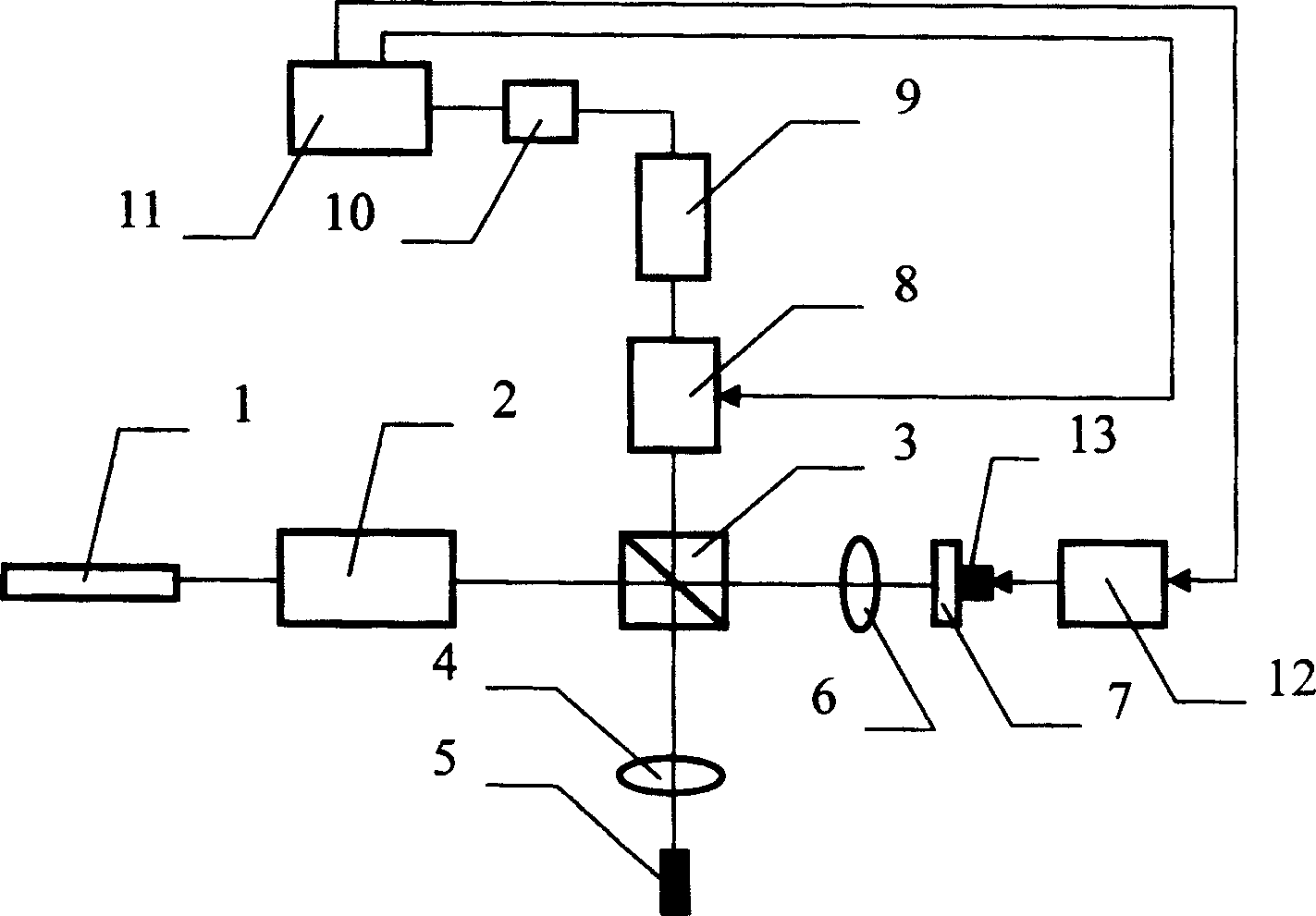
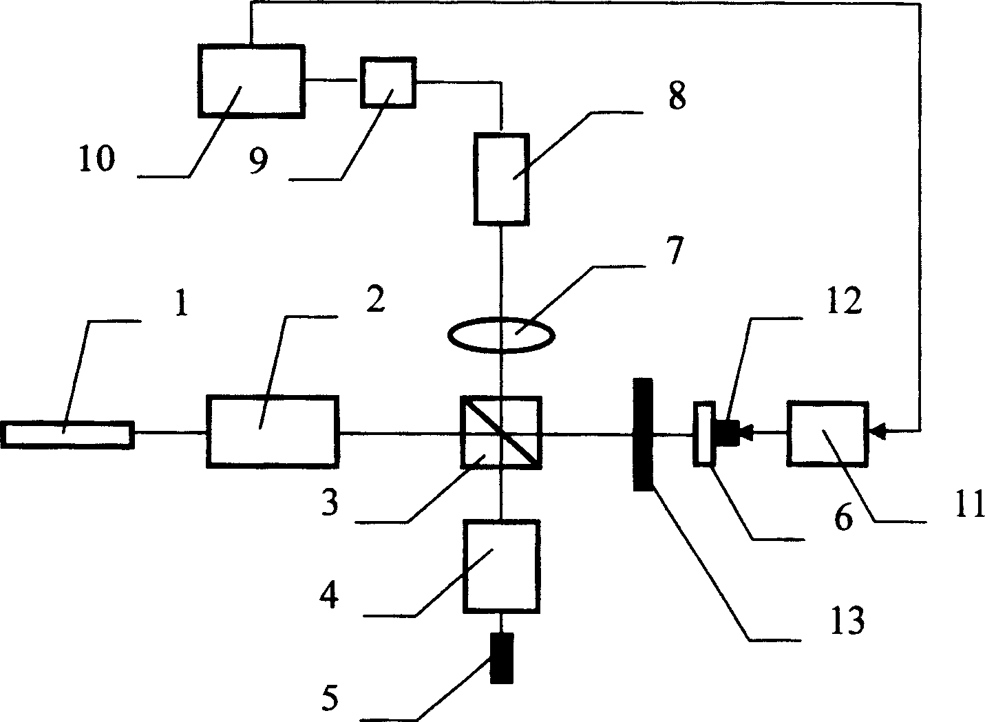
[0042] see first image 3 , image 3 It is a structural schematic diagram of the optical fiber connector end face geometric parameter measuring instrument of the present invention. As can be seen from the figure, the optical fiber connector end face geometric parameter measuring instrument of the present invention adopts a Twyman-Green interferometer structure, including a light source 1, and a collimating beam expander system 2 is sequentially arranged on the same optical axis along the forward direction of the emitted light beam of the light source 1, and is divided into two parts. A beam filter 3, a shutter 13, and a reference plane mirror 6 bonded on a piezoelectric ceramic 12. In the direction passing through the center of the beam splitter 3 and perpendicular to the light beam emitted by the light source 1, one end of the beam splitter 3 is provided with the optical fiber connector 5 and the optical system 4 to be tested, and the other end is provided with a lens 7 and ...


PUM


Abstract

A measurer applying Twyman-Green interferometer structure is featured as having light source, setting collimation extender system, beam-splitter, light chopper and plane reflector bound on piezoelectric ceramics in sequence on th same optical axis; setting optical fibre connector at one end of beam splitter and lens as well as detector on another end, connecting detector to computer through A / D converter and connecting computer to the piezoelectric ceramics through driving circuit.

Description

technical field [0001] The invention relates to an optical fiber connector, and relates to an end face geometric parameter measuring instrument of the optical fiber connector and a measuring method for the end face geometric parameter of the optical fiber connector. Background technique [0002] Fiber optic connectors are one of the most widely used basic components in optical communications, fiber optic sensors and other fiber optic applications. The geometric parameters of the end face of the fiber optic connector determine its technical performance such as insertion loss, return loss, repeatability and interchangeability. Therefore, it is very necessary to detect the geometric parameters of the end face of the optical fiber connector in the process of grinding production, finished product inspection and assembly. The geometric parameters of the end face of the optical fiber connector mainly include the radius of curvature, the eccentricity of the vertex of the spherical ...

Claims


Application Information

Patent Timeline
Patent Type & Authority Patents(China)
IPC IPC(8): G01M11/02G02B6/36G02B6/38G01M11/00G01M99/00
Inventor 路元刚王向朝钟向红
Owner SHANGHAI INST OF OPTICS & FINE MECHANICS CHINESE ACAD OF SCI
Why Eureka
Try Eureka