Motor control device and method

A technology of motor control and control section, applied in motor control, AC motor control, electronic commutation motor control, etc., can solve the problems of shorter pulse width, lower duty ratio, and inability to input and respond.

Inactive Publication Date: 2006-10-25
SANYO ELECTRIC CO LTD +1
View PDF1 Cites 0 Cited by
  • Summary
  • Abstract
  • Description
  • Claims
  • Application Information

AI Technical Summary

Problems solved by technology

[0009] However, in the above-mentioned motor control device, in order to reduce the voltage applied to the motor, when the pulse width of the switching signal is shortened to reduce the duty ratio, the pulse width of the pulse-shaped induced voltage corresponding to the switching signal is also shortened. , when the pulse width of the induced voltage is too short, the input and response cannot be handled according to the characteristics of the rotor position detection circuit, and the rotor position cannot be estimated

Method used


Image

  • Motor control device and method
  • Motor control device and method
  • Motor control device and method

Examples


no. 2 Embodiment approach

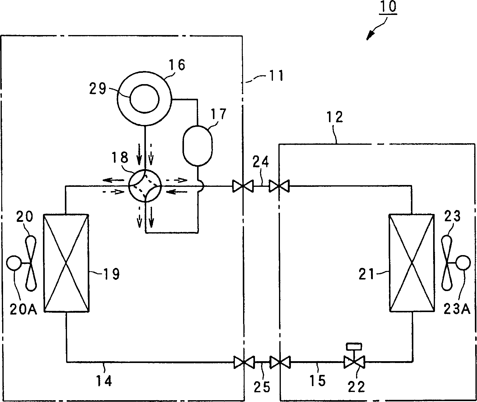
[0061] In the first embodiment described above, the case where the control unit 34 continuously decreases the carrier frequency B as the duty ratio decreases, while in the second embodiment, the control unit causes the carrier frequency B to decrease as the duty ratio decreases. The carrier frequency drops in stages. Furthermore, the configuration of the system is the same as that of the first embodiment figure 1 with figure 2 It is the same, so the description is omitted.

[0062] Figure 5 It is an explanatory diagram showing the carrier frequency corresponding to the duty ratio.

[0063] First of all, it is the same as that of the first embodiment Figure 4 Similarly, the control unit 34 sets the threshold value A (for example, 5 [%]) according to the duty ratio of the PWM switching signal.

[0064] Then, the control unit 34 lowers the carrier frequency B'in stages as the duty ratio decreases, so as to generate PWM with a duty ratio corresponding to the applied voltage (line...


PUM


Abstract

PURPOSE: A motor control apparatus and a motor control method are provided to estimate position of a rotor even when a control for lowering voltages applied to the motor is performed. CONSTITUTION: A motor control apparatus(100) controls a voltage applied to a DC motor(29) by estimating position of a rotor(31) on the basis of an organic voltage of the DC motor driven by an inverter(32), and outputting a pulse width modulated switching signal to the inverter on the basis of the result of the estimation. The motor control apparatus includes a control unit(34) for controlling carrier frequency of the pulse width modulated switching signal such that a switching signal has a pulse width larger than a predetermined pulse width, when the switching signal having a duty ratio corresponding to the voltage applied to the DC motor is generated.

Description

Technical field [0001] The invention relates to a motor control device and a motor control method, in particular to a motor control device and a motor control method for estimating the position of a rotor. Background technique [0002] Conventionally, it is known to estimate the position of the rotor based on the induced voltage of the non-energized phase of the motor driven by the inverter, and based on the estimation result, output a pulse width modulated switching signal to the inverter to control the voltage applied to the motor. Motor control device (for example, refer to Patent Document 1). [0003] As the above-mentioned motor, a brushless DC motor is known, which generally uses a control method (sensorless control method) that does not provide a sensor for detecting the rotor position, but detects an induced voltage and estimates the rotor position. In addition, in the motor control device, for example, a 120-degree energized rectangular wave drive method for controlling ...

Claims


Application Information

Patent Timeline
Patent Type & Authority Patents(China)
IPC IPC(8): H02P27/04H02P6/08H02P6/06H02P6/18H02P6/182
CPCH02M7/527H02P6/085H02P6/182H02P2209/09Y10S388/912Y10S388/9281
Inventor 中山义纪高田元宫内拓
Owner SANYO ELECTRIC CO LTD
Why Eureka
Try Eureka