Vector controller without speed sensor

A vector control and estimated value technology, which is applied in the field of speed sensorless vector control devices, can solve the problems that the magnetic flux speed cannot be calculated, the secondary magnetic flux cannot be calculated, and the speed is difficult to estimate stably.

Inactive Publication Date: 2005-09-07
FUJI ELECTRIC CO LTD
View PDF0 Cites 0 Cited by
  • Summary
  • Abstract
  • Description
  • Claims
  • Application Information

AI Technical Summary

Problems solved by technology

Therefore the secondary flux cannot be calculated from the primary voltage, neither the estimated flux nor the estimated speed
That is to say, the deviation between the estimated flux and its actual value and the deviation between the estimated velocity and its estimated value are not equal to zero, and cann

Method used


Image

  • Vector controller without speed sensor
  • Vector controller without speed sensor
  • Vector controller without speed sensor

Examples


Embodiment Construction

[0058] Embodiments of the present invention are described below with reference to the drawings.

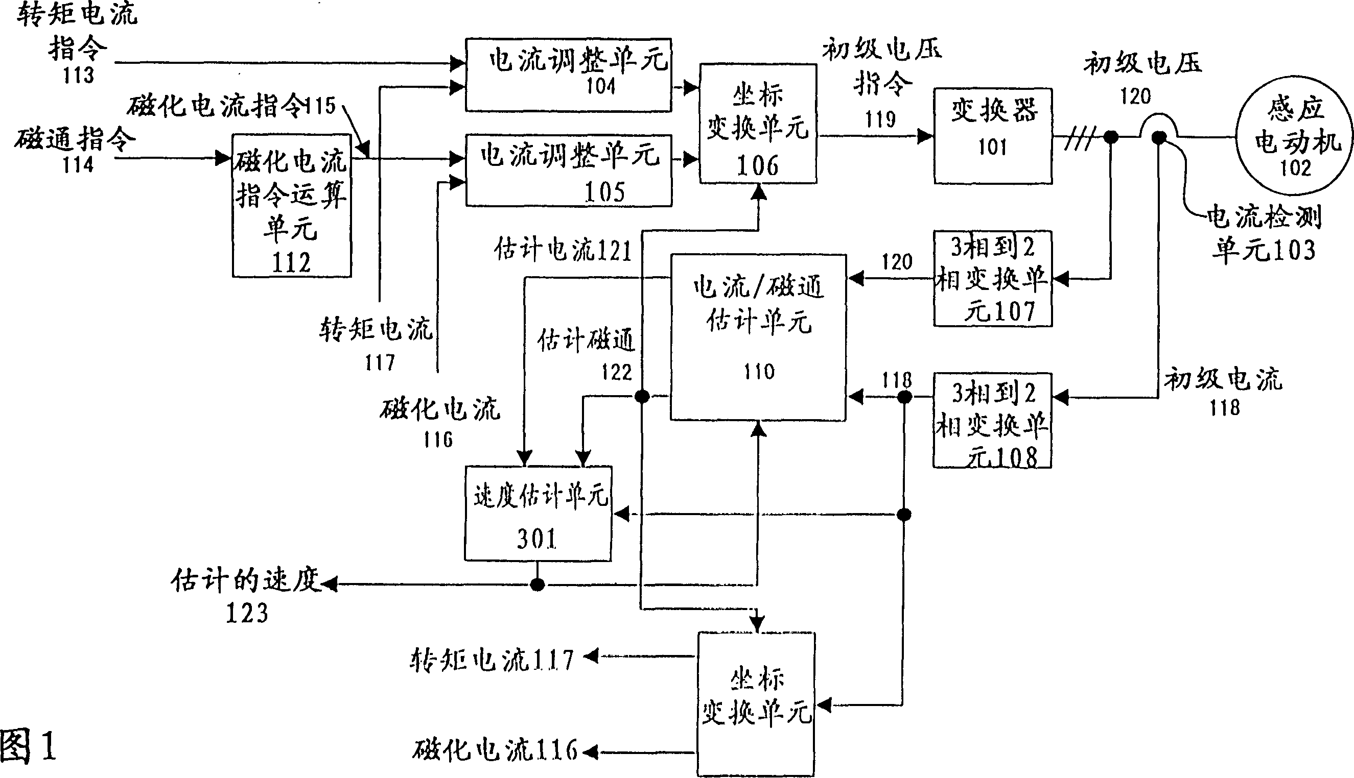
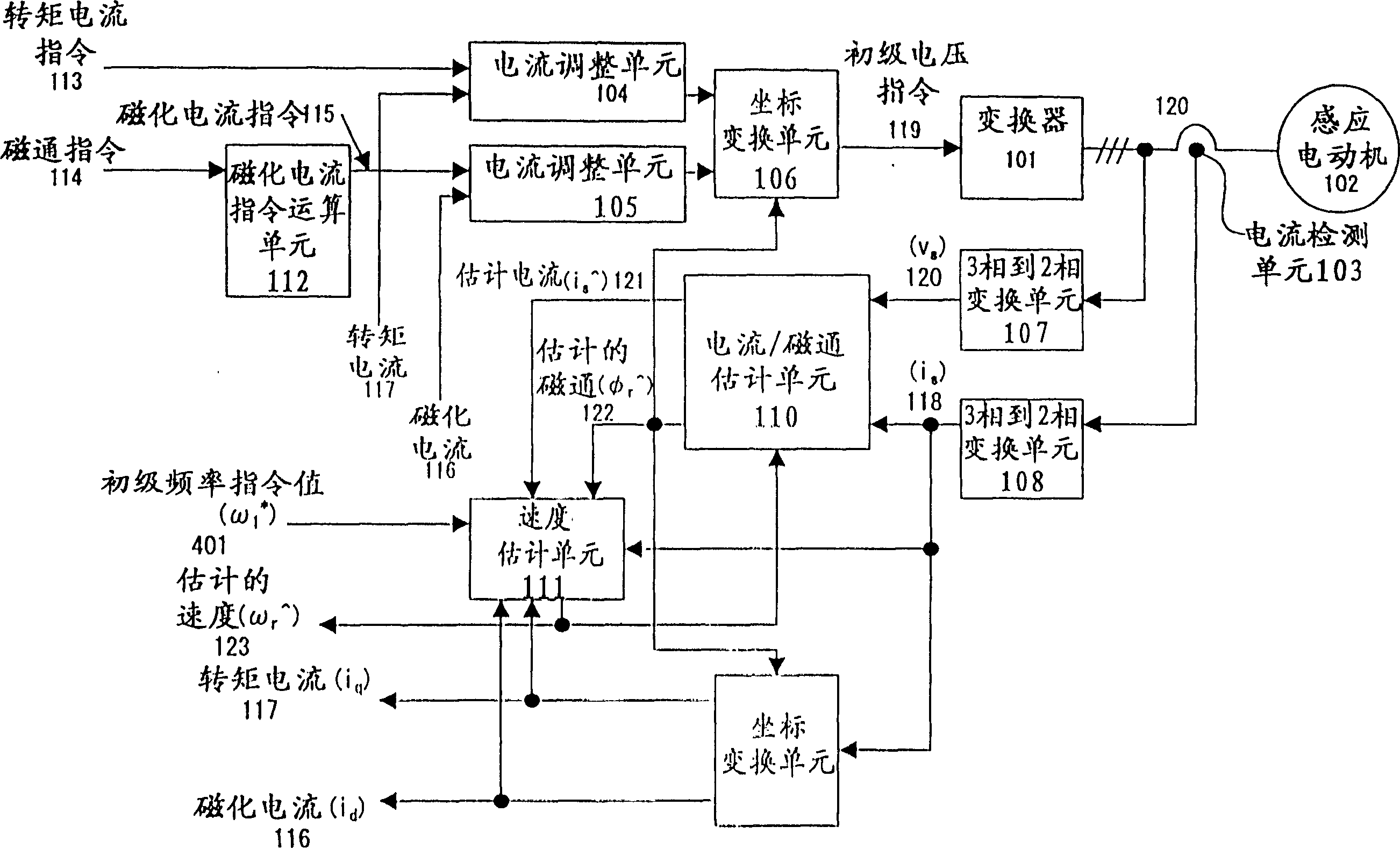
[0059] attached image 3 Shown is a control block diagram of an embodiment of the invention. The difference from the block diagram shown in FIG. 1 lies in the structure of the speed estimation unit 111 . The speed estimation unit 111 further receives the primary frequency command value (ω 1 * ) 401, magnetizing current (i d ) 116 and torque current (i q )117. The other units are the same as those shown in FIG. 1 . Therefore, the same reference numerals as those shown in FIG. 1 are assigned, and their explanations are omitted here.

[0060] FIG. 4 shows the internal structure of the speed estimation unit 111 .

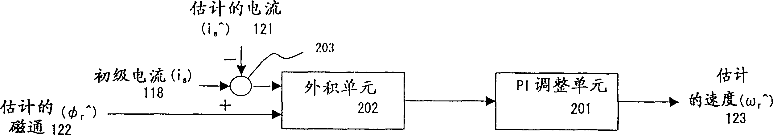
[0061] Refer to the attached figure 2 Describe the structure. with attached figure 2 In comparison, the structure shown in FIG. 4 further includes addition / subtraction units 205 and 305, multiplication units 306 and 309, gain element 304, absolute value operation...


PUM


Abstract

A control apparatus for estimating the flux, the current, and the speed of an AC motor using the current and the voltage, and controlling the vector of an AC motor using the estimated speed, a flux command, and a torque current command. The speed is estimated by adding a product of the deviation between the actual value and the estimated value of a magnetization current, the level of a torque current correspondence value, the sign correspondence value of a primary frequency command value, and a gain to an outer product of an estimated current deviation and an estimated flux. Thus, a stable speed estimating operation can be performed to successfully operate the motor in a low speed area in which a voltage frequency applied to the motor is extremely low.

Description

technical field [0001] Generally, the present invention relates to a speed sensorless vector control apparatus capable of controlling the vector of an AC motor such as an induction motor or the like but having no speed sensor. Background technique [0002] In known vector control of high-performance and high-precision systems for controlling induction motors, information about the speed of the motor is required, and such information is usually obtained by a pulse generator (PG) or the like. However, it is desirable to implement speed sensor vector control with a variable speed drive system that can perform torque control and obtain maximum torque over a wide operating range without requiring high performance conventional speed sensor vector control Restrictions on installing the speed sensor are controlled, and it is also possible to simplify wiring, reduce costs, etc. [0003] Accompanying drawing 1 is shown as the functional block diagram of the conventional speed sensorl...

Claims


Application Information

Patent Timeline
IPC IPC(8): H02P21/00H02P21/04H02P21/13H02P21/14H02P21/18H02P21/22H02P21/24H02P23/03H02P23/07H02P23/12H02P23/14H02P27/04
CPCH02P21/146H02P21/0042H02P21/18H02P21/26
Inventor 田岛宏一海田英俊
Owner FUJI ELECTRIC CO LTD
Why Eureka
Try Eureka