Dynamic testing loading unit for MEMS disc or device

A technology of dynamic testing and loading devices, which is applied in the direction of measuring devices, electrical devices, microstructure devices, etc. It can solve the problems of being unsuitable for dynamic testing of small specimens, unsuitable for dynamic testing of MEMS wafers or devices, etc., and achieves a controllable Effect

Inactive Publication Date: 2006-11-01
HUAZHONG UNIV OF SCI & TECH
View PDF0 Cites 0 Cited by
  • Summary
  • Abstract
  • Description
  • Claims
  • Application Information

AI Technical Summary

Problems solved by technology

The disadvantages of traditional loading devices are: ①The application of these loading devices generally requires the sensor to be installed on the specimen, so the specimen needs to have a large enough size, and it is also necessary to ensure that the installation of the sensor is not enough to affect the dynamic test of the specimen The accuracy of the vibration and measurement system provided by these loading devices is not suitable for dynamic testing of tiny specimens, so it is not suitable for small specimens such as MEMS wafers or devices.
②The traditional vibration loading test is carried out in the atmospheric environment or even the harsh working environment, which is not suitable for the dynamic test of the test pieces with strict environmental requirements such as MEMS wafers or devices

Method used


Image

  • Dynamic testing loading unit for MEMS disc or device
  • Dynamic testing loading unit for MEMS disc or device

Examples


Embodiment Construction

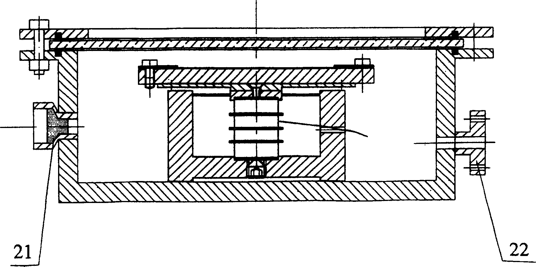
[0012] Depend on figure 1 and figure 2 As shown, a dynamic test loading device for a MEMS wafer or device includes a light-transmitting sheet 9, a cavity 1, a bracket 5 and a support plate 13, and a sealing ring 7 is placed between the light-transmitting sheet 9 and the opening end face of the cavity 1 , and connected to the flange 16 through the sealing ring 8, the flange 16 is fixed to the opening end face of the vacuum chamber 1 through the bolt 17 and the nut 18, the light-transmitting sheet 9 and the chamber 1 form a sealed chamber, which is a MEMS circle for dynamic testing chip or device to provide a closed environment.

[0013] An electrode 21 is installed on the cavity 1, and an air charging port 6, a vacuum port 20 and a vacuum gauge interface 22 are opened. The bracket 5 can be fixed on the base of the cavity 1 by bolts 2, and the adjusting screw 3 is installed in the base of the bracket 5. , the piezoelectric ceramic (PZT) 4 is placed in the bracket 5, the lower...


PUM


Abstract

The invention discloses a dynamic test loading device for MEMS wafers or devices. The structure of the device is as follows: a light-transmitting sheet is placed on the opening end surface of a cavity to form a sealed cavity with the cavity, and electrodes are installed on the cavity. There are air charging port, vacuum port and vacuum gauge port, the bracket is fixed on the base of the cavity, the adjusting screw is installed in the base of the bracket, the piezoelectric ceramic is placed in the bracket, the lower end is connected with the adjusting screw, and the upper end is connected with the bracket Then, the support plate is fixed on the bracket, and the disc bead is fixed with the support plate. The device can obtain precise vibration frequency and amplitude through piezoelectric ceramics, and can change the frequency and amplitude in a relatively large range, and is easy to control. It can provide different vacuum degrees for MEMS wafer or device testing. temperature and different vibration state environments.

Description

technical field [0001] The invention relates to a loading device, in particular to a loading device applied to the dynamic testing of MEMS (Micro-electromechanical systems, micro-electromechanical systems) wafers or devices. Background technique [0002] The loading device for the dynamic test of the specimen, that is, the vibrator is a device that converts electrical energy into mechanical energy and provides vibration to the specimen. In recent years, a large number of MEMS devices have appeared and been applied. In order to obtain the modal parameters, it is necessary to load them with excitation and measure their responses. Traditional vibration exciters have been widely used in vibration loading tests of aircraft, missiles, ships, machine tools, bridges, etc., and have also been applied to local components that need to provide vibration and other forms of loading for testing. The disadvantages of traditional loading devices are: ①The application of these loading device...

Claims


Application Information

Patent Timeline
Patent Type & Authority Patents(China)
IPC IPC(8): B81C5/00G01H11/06B81C99/00
Inventor 汪学方史铁林张鸿海刘胜施阳和甘志银谢勇君
Owner HUAZHONG UNIV OF SCI & TECH
Why Eureka
Try Eureka