
Trench Schottky rectifier

A rectifier and channel technology, applied in the field of Schottky barrier rectifiers, can solve the problems of increasing the complexity of the manufacturing process of hierarchical doping distribution and the like

Inactive Publication Date: 2006-11-22
GEN SEMICON
View PDF2 Cites 0 Cited by
  • Summary
  • Abstract
  • Description
  • Claims
  • Application Information

AI Technical Summary

Problems solved by technology

[0009] Unfortunately, the need for graded doping profiles adds complexity to the manufacturing process, and the resulting expense

Method used


Image

  • Trench Schottky rectifier
  • Trench Schottky rectifier
  • Trench Schottky rectifier

Examples


Embodiment Construction

[0035] Preferred embodiments of the present invention will be described in detail below with reference to the accompanying drawings. However, the invention may also be embodied in different ways and should not be limited to the specific embodiments set forth herein.

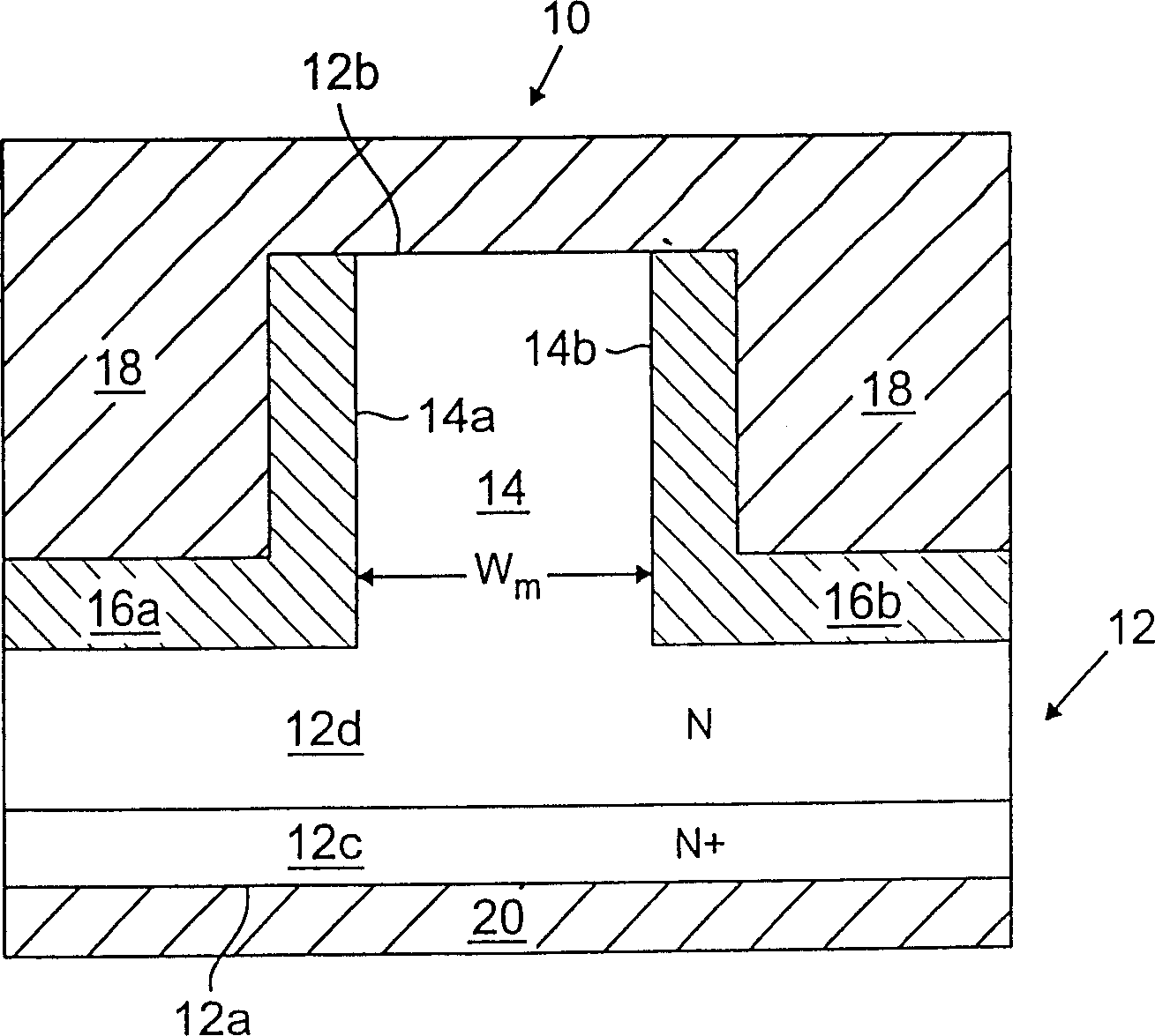
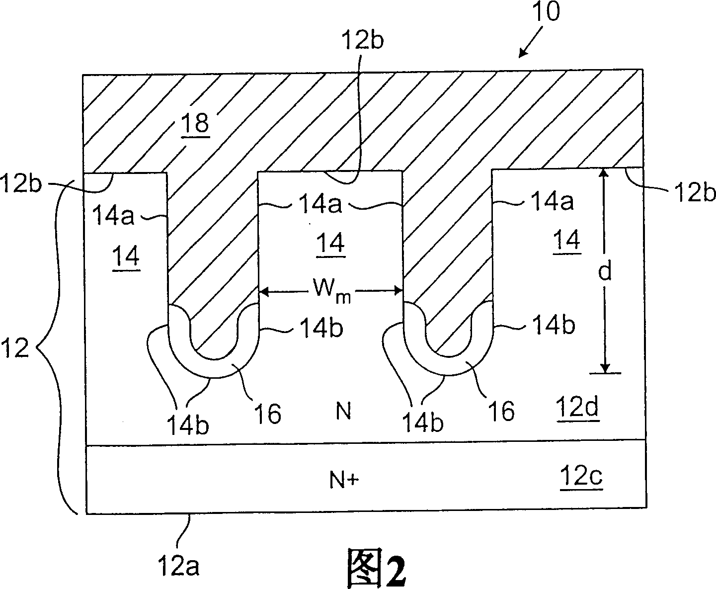
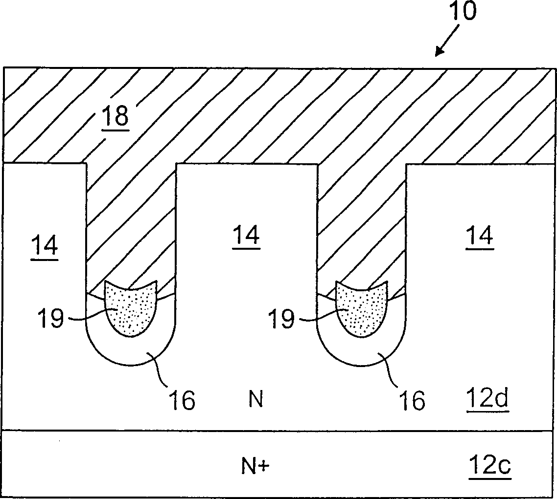
[0036] Referring now to FIG. 2, there is shown a Schottky barrier rectifier in accordance with the present invention. The rectifier 10 includes a semiconductor region 12 of a first conductivity type (usually an N-type conductivity type), and the semiconductor region has opposite first and second surfaces 12a and 12b. The substrate semiconductor region 12 preferably includes a relatively highly doped cathode region 12c (shown as N+) bordering the first side 12a. As shown, the cathode region 12c is doped to approximately 5×10 19 / cm 3 The doping concentration of the first conductivity type. A drift region 12d (shown as N) of the first conductivity type preferably extends from the cathode region 12c to the second ...


PUM


Abstract

A Schottky rectifier is provided. The Schottky rectifier includes: (a) a semiconductor region having a first face and an opposite second face, the semiconductor region including a cathode region of the first conductivity type bordering the first face and a cathode region bordering the second face a drift region of the first conductivity type, the drift region having a lower net doping concentration than the cathode region; (b) one or more channels extending from the second face into the semiconductor region and defined within the semiconductor region One or more mesa transistors; (c) an insulating region bordering the semiconductor region at the lower portion of the channel; (d) an anode (i) bordering the semiconductor region at the second face and forming a Schottky A rectifying contact (ii) borders the semiconductor region in the upper portion of the trench and forms a Schottky rectifying contact, and (iii) borders the insulating region in the lower portion of the trench.

Description

technical field [0001] The present invention relates to rectifiers, and more particularly to Schottky barrier rectifying devices, and methods of forming these devices. Background technique [0002] A rectifier has relatively low resistance to current flow in the forward direction and high resistance to current flow in the reverse direction. Schottky barrier rectifiers are a type of rectifier that have been used in switch mode power supplies and other high speed power switching applications such as motor drives as output rectifiers. These devices are capable of delivering large amounts of forward current and support large reverse cut-off voltages. [0003] U.S. Patent No. 5,365,102 to Mehrotra et al., entitled "Schottky Barrier Rectifier With MOS Channel," the entire contents of which are hereby incorporated by reference, discloses Schottky Barrier Rectifiers with breakdown voltage ratios of Theoretically higher can be obtained by the ideal discontinuous parallel plane PN j...

Claims


Application Information

Patent Timeline
Patent Type & Authority Patents(China)
IPC IPC(8): H01L29/872H01L29/47
CPCH01L29/872H01L29/8725
Inventor 石甫渊陈世冠苏根政崔炎曼
Owner GEN SEMICON
Learn More