Diffusing and spraying combustion system of IC engine

A spray combustion, internal combustion engine technology, applied in the direction of internal combustion piston engines, charging systems, combustion engines, etc., can solve the problems of short penetrating distance of umbrella-shaped spray, too thick circular distribution of mixed gas, unevenness, etc., and achieve fast spray dispersion speed , Large spatial range of distribution, and the effect of increased power

Inactive Publication Date: 2006-12-06
DALIAN UNIV OF TECH
View PDF0 Cites 0 Cited by
  • Summary
  • Abstract
  • Description
  • Claims
  • Application Information

AI Technical Summary

Problems solved by technology

[0003] In order to solve the problems of too thick mixture and uneven distribution at the landing point of the porous spray, and the short penetrating distance of the umbrella-shaped spray, the invention provides a diffusion spray combustion system for an internal combustion engine, which can provide good atomization performance , Spatial distribution is uniform, the spray will not accumulate at the landing point, but part of it will be rebounded, and part will be quickly dispersed along the diffusion surface to achieve secondary atomization

Method used


Image

  • Diffusing and spraying combustion system of IC engine
  • Diffusing and spraying combustion system of IC engine
  • Diffusing and spraying combustion system of IC engine

Examples


Embodiment Construction

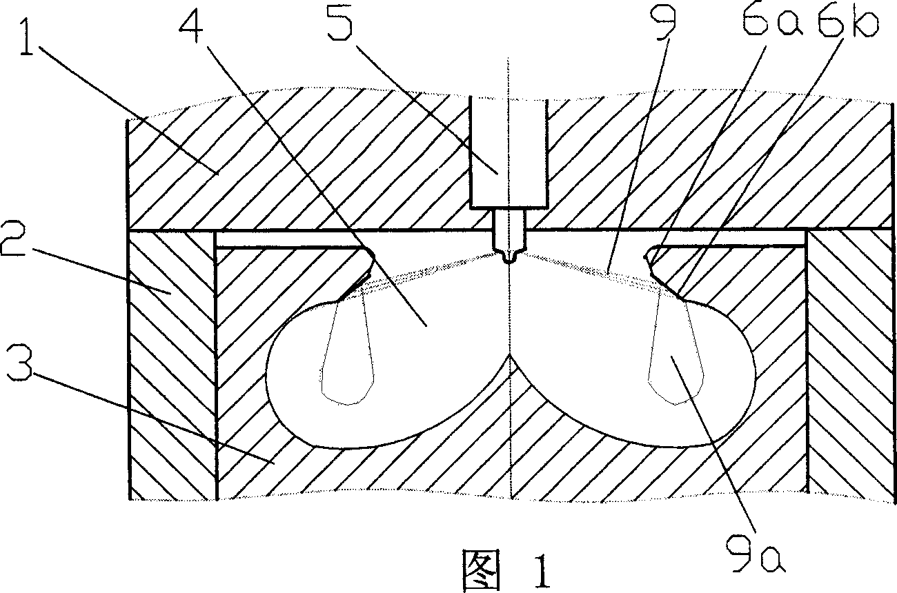
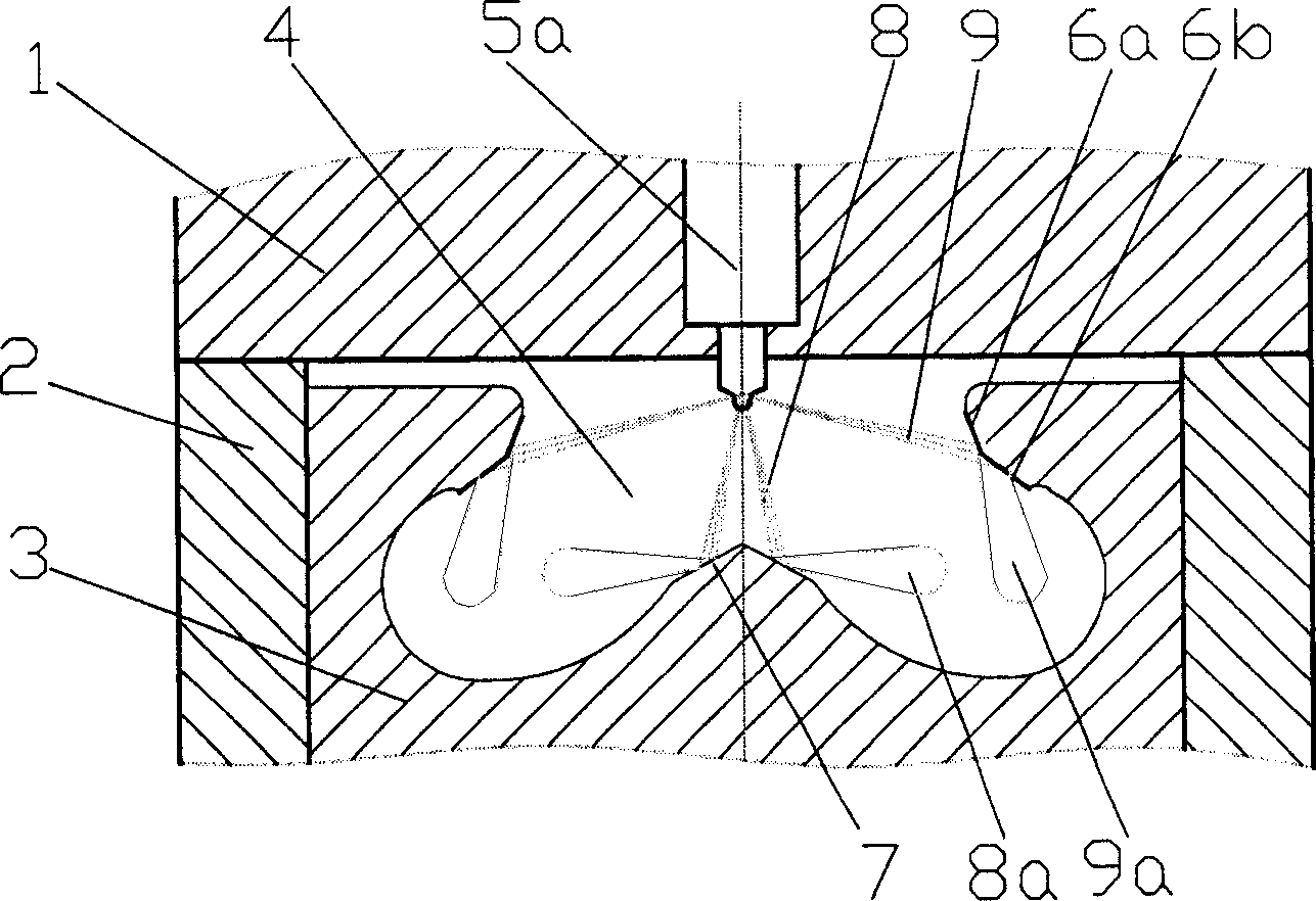
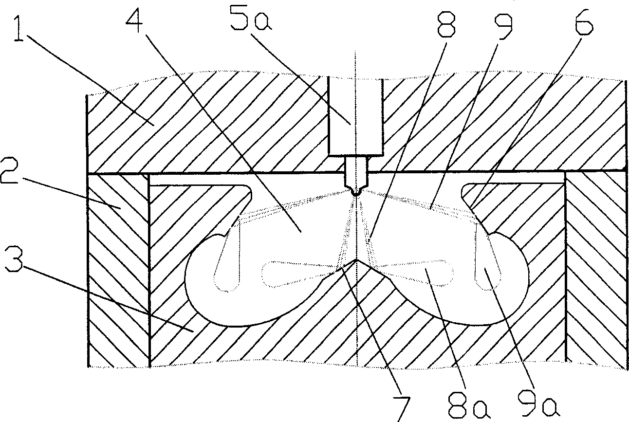
[0011] In the embodiment shown in Figures 1, 2, and 3, a main combustion chamber is composed of a cylinder head 1, a cylinder liner 2 and a piston 3, and the combustion chamber 4 arranged on the top of the piston should cooperate with the oil beam of the injector. , the spray diffusion surface provided at the closing part of the combustion chamber 4 is a conical surface, and the oil beam 9 of the injector is directly sprayed to the conical surface.

[0012] In Fig. 1, the spray diffusion surface at the mouth of the combustion chamber 4 adopts an upper cone surface 6a and a lower cone surface 6b, and the oil beam 9 of the single-row nozzle injector 5 is directly sprayed on the upper cone surface 6a and the lower cone surface 6b , forming a diffused oil beam 9a with a wider distribution range.

[0013] exist figure 2 Among them, the spray diffusion surface at the mouth of the combustion chamber 4 also adopts an upper cone surface 6a and a lower cone surface 6b, and a protrusion...


PUM


Abstract

A diffusion spray type combustion system for IC engine features that a spray diffusing conic surface is arranged at the diameter-reduced position of combustion chamber for spraying the beam from the oil sprayer directly to it, so generating an oil beam diffused in wire range and quickly forming a relatively uniform gas mixture. Its advantages are quick and full combustion, low oil consumption, high power and less pollution.

Description

technical field [0001] The invention relates to a diffusion spray combustion system of an internal combustion engine, which belongs to the field of engine mixture gas formation and combustion. Background technique [0002] At present, the excess air coefficient of the diesel engine is relatively large, but it is easy to emit black smoke. The main reason is that the porous spray is not uniform in the circumferential direction, and an over-concentrated area is generated at the spray point. A part of the spray accumulates near the impact point or forms an oil film, and the other part rebounds and spreads to the circumference, because it is close to the wall of the combustion chamber and the amount of air involved is small. These factors constitute the main cause of carbon formation on the wall of the combustion chamber despite the large excess air coefficient of the diesel engine, but the incomplete combustion, black smoke and high hydrocarbon emissions. In order to solve this...

Claims


Application Information

Patent Timeline
Patent Type & Authority Patents(China)
IPC IPC(8): F02B23/06F02F3/26F02M61/14
CPCY02T10/125Y02T10/12
Inventor 隆武强冯立岩杜宝国魏胜利陈雷
Owner DALIAN UNIV OF TECH
Why Eureka
Try Eureka