Supply and discharge method for supercharged fluid

A technology for pressurizing fluids, vents, used in connections with fluid cut-off devices, fluid pressure converters, transportation and packaging, etc., can solve problems such as pressure oil leakage

Inactive Publication Date: 2006-12-06
KOSMEK LTD (JP)
View PDF1 Cites 1 Cited by
  • Summary
  • Abstract
  • Description
  • Claims
  • Application Information

AI Technical Summary

Problems solved by technology

This causes pressure oil to easily leak from the sealing portion of the front end of the socket and plug

Method used


Image

  • Supply and discharge method for supercharged fluid
  • Supply and discharge method for supercharged fluid
  • Supply and discharge method for supercharged fluid

Examples


Embodiment Construction

[0024] After this, an exemplary embodiment of the invention is described with reference to FIGS. 1 to 4 .

[0025] This embodiment exemplifies a case of the present invention, which is applicable to a method of supplying and discharging hydraulic oil between a workbench and a workbench of a machining center.

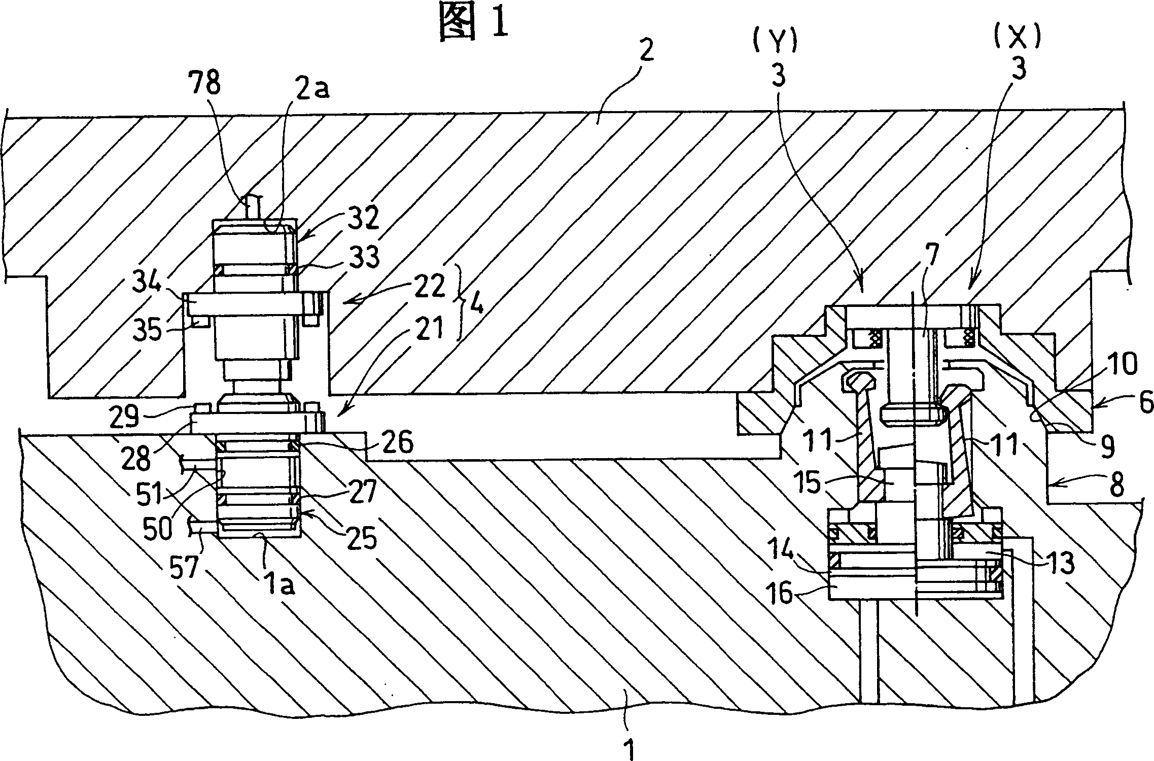
[0026] First, the entire structure of the supply and discharge device, which uses the above-mentioned supply and discharge method based on the schematic diagram of FIG. 1, will be described.

[0027] Multiple sets of locking devices 3 and multiple sets of quick couplers 4 are arranged on the workbench (first assembly) 1 and the working board frame (second assembly) 2 of the machining center. Here, hydraulic chucks and workpieces (both are not shown in the figure) are arranged on the upper surface of the working board frame 2 . And hydraulic oil is supplied to or discharged from the hydraulic chuck through the quick coupler 4, so that the workpiece can be fixed or releas...


PUM


Abstract

When supplying pressurized oil from a first port (51) to a second port (78), first, a pallet (2) is lowered to a table (1). And a first stop member (45) of a socket (21) is brought into butting contact with a second stop member (67) of a plug (22), thereby forming a contact gap (B) between the second stop member (67) and a check member (72) within a check valve chamber (70) of the plug (22). Next, the pallet (2) is fixed to the table (1) by a locking device (3). Subsequently, the pressurized oil at the first port (51) is supplied to the second port (78) via the check valve chamber (70) and thereafter is discharged to an exterior area.

Description

technical field [0001] The present invention relates to a method of supplying and discharging pressurized fluid, for example, it relates to a method suitable for supplying and discharging pressurized oil to a working pallet detachably fixed to the table of a machine tool. Background technique [0002] A general example of such a pressurized fluid supply and discharge method is disclosed in Japanese Patent Specification No. 3-47975. This general technical arrangement is as follows. [0003] When connecting a quick coupler having a receptacle and a plug, an air actuator advances the receptacle closer to the plug, thereby first sealing the front of the receptacle and the front of the plug. The first stop element in the socket then comes into mating contact with the second stop element in the plug, thereby forcing the first non-return element in the socket and the second non-return element in the plug to open. And the air actuator applies a thrust which keeps the receptacle en...

Claims


Application Information

Patent Timeline
Patent Type & Authority Patents(China)
IPC IPC(8): F15B3/00B23Q1/72B23Q3/00F16L29/04F16L37/30
CPCB23Q1/0018B23Q1/0072F16L29/04Y10T137/87973Y10T137/87949Y10T137/0318
Inventor 有里明
Owner KOSMEK LTD (JP)
Why Eureka
Try Eureka