Switching mechanism of protective switch

A switch mechanism and protection switch technology, applied in the direction of protection switch operation/release mechanism, etc., can solve the problem of the switch device becoming larger, and achieve the effect of reducing the total heat, ensuring the transition of small resistance, and reducing the temperature

Inactive Publication Date: 2006-12-06
MOELLER GEBAUDEAUTOMATION KG
View PDF2 Cites 0 Cited by
  • Summary
  • Abstract
  • Description
  • Claims
  • Application Information

AI Technical Summary

Problems solved by technology

[0007] However, the bulky contact pieces must have large dimensions, which will eventually lead to an increase in the size of the entire switchgear

Method used


Image

  • Switching mechanism of protective switch
  • Switching mechanism of protective switch
  • Switching mechanism of protective switch

Examples


Embodiment Construction

[0041] Description of preferred embodiments

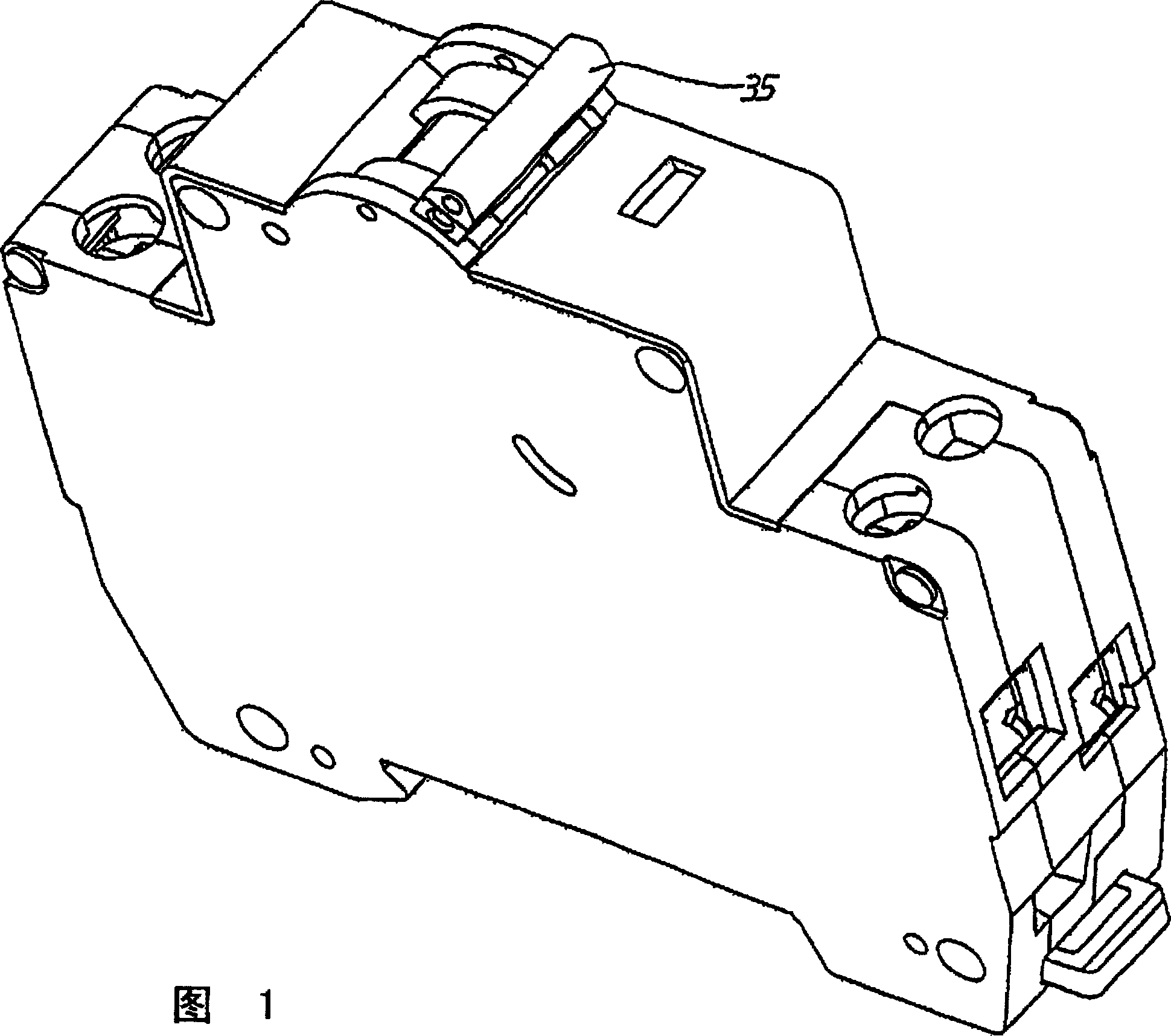
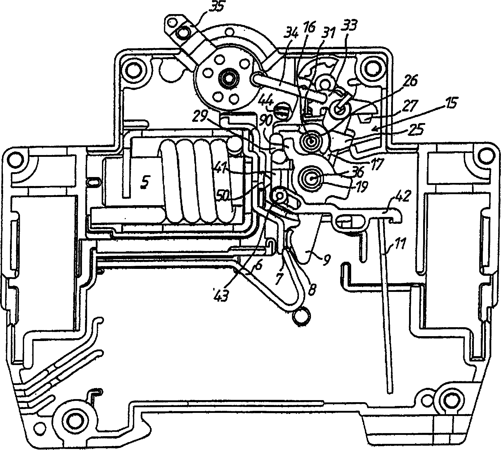
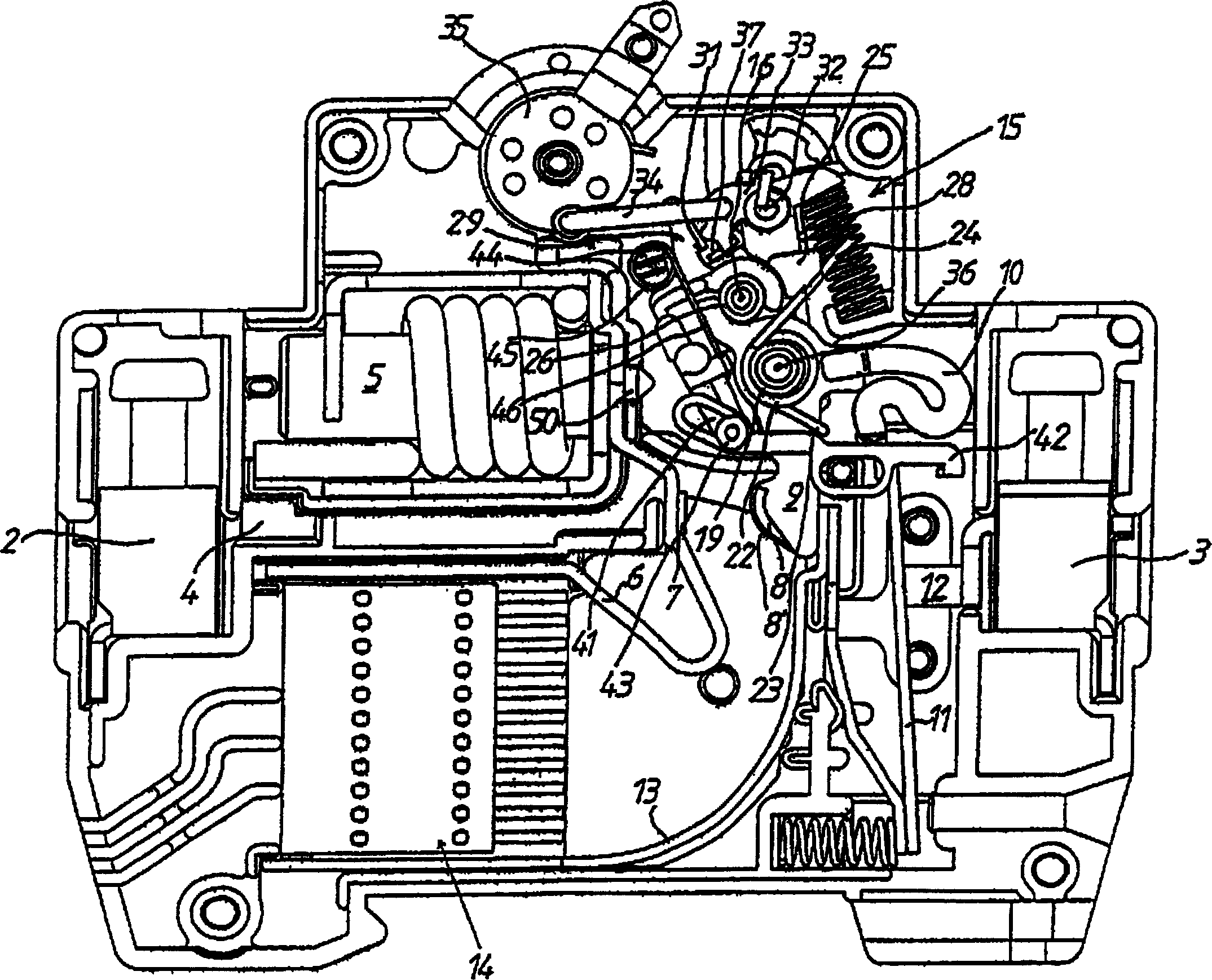
[0042] FIG. 1 shows the housing of a circuit breaker, which has two switching sections, namely a section for the phase conductor L of a single-phase AC circuit and a section for the associated neutral line N. In FIG. Each switching section consists of a terminal clamp 2 for the incoming conductor and a terminal clamp 3 for the outgoing conductor (see image 3 ). The first terminal clip 2 is connected to a current conductor bar 4 which is connected to a first coil end of a movable armature release 5 . The second coil end of the movable armature release 5 is connected to a further current conductor 6 which has a fixed contact 7 . The movable contact 8 which is in contact with the fixed contact in the switched-on state is fixed on the switching bridge 9 . The switch bridge 9 is connected to the free end of a bimetal 11 via a flexible conductive cable 10 . The second end of the bimetal strip 11 , which is held stationary relative t...


PUM


Abstract

A switch mechanism for protecting switches has two common switch sectors and each has a movable contactor fixed on the switch bridge, among which a support is rotably set up around the mechanism rotating shaft fixed on the case, there is an extended middle wall vertical to the said shaft, an inserted holder is set mounted on the bearing block by its hole and a shoulder in the zone of the upper end of a plug rotably supported around the plug rotating shaft at the upper end of the middle wall and a hook is set up of coupling the plug with the operational rod. A switch bridge rotating shaft is staggeredly is set up in the direction of the moving contactor relative to the mechanism shaft.

Description

technical field [0001] The invention relates to a switching mechanism for a protective switch, which has two common switching sections for switching, each section has a movable contact fixed on the switching bridge, in which there is a fixed A bracket that is rotatably supported by the mechanism shaft on the housing. The bracket has an intermediate wall extending perpendicular to the mechanism shaft. A cylinder, a support stop concentric with the mechanism shaft, and a foot are each formed on its two end faces. Support, the switch bridge is mounted on the cylinder with its hole and the torsion spring is mounted on the cylinder with its ring, so that the longitudinal axis of the cylinder constitutes the rotation axis of the switch bridge, wherein the first leg of the torsion spring is supported on the switch bridge and the second leg Bearing on the leg supports, whereby the switch bridge is continuously loaded in the direction of bearing stops with mutually different strengths,...

Claims


Application Information

Patent Timeline
IPC IPC(8): H01H71/12
Inventor A・尼兹纳
Owner MOELLER GEBAUDEAUTOMATION KG
Why Eureka
Try Eureka