Eureka AIR delivers breakthrough ideas for toughest innovation challenges, trusted by R&D personnel around the world.

Small displacement sensing method and device

A sensing method and technology of small displacement, applied in the direction of measuring device, using electric device, electromagnetic measuring device, etc., can solve the problems of difficult industrial manufacturing, cannot be made too small, small size of the sensor, etc., to facilitate industrial implementation, The materials are easy to obtain and the effect of the process is simple

Inactive Publication Date: 2006-12-13
唐荣华
View PDF0 Cites 0 Cited by
  • Summary
  • Abstract
  • Description
  • Claims
  • Application Information

AI Technical Summary

Problems solved by technology

It can be made very small, but the cost is very high
3. Optical fiber sensing method, which measures the strain through the optical change caused by material deformation, which requires CCD imaging components, and the cost is also very high
4. Resistance ruler, which is a very high-precision length measurement method, but the size is large
[0003] From the above displacement sensing method, we can see that although some existing sensors have mature technology and low cost, they cannot be made too small; those that can be made smaller, the cost is very high
However, existing sensors are generally developing in the direction of high reliability and high precision, and the structure is becoming more and more complex. The materials or components used in the sensors are becoming more and more expensive. At the same time, industrial manufacturing is difficult, resulting in higher and higher overall prices and costs.
For applications that do not require high measurement accuracy but require a small sensor size, it is difficult to find a low-cost sensor that is suitable for the application

Method used


Image

  • Small displacement sensing method and device
  • Small displacement sensing method and device

Examples


Embodiment 1

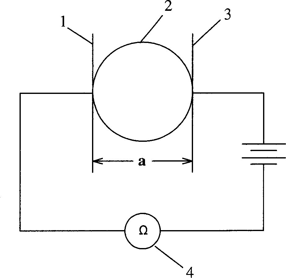
[0021] See figure 1 A deformation medium 3 with a certain resistance value is defined between the two conductors 1 and 2. The deformation medium 3 can be a liquid or colloidal medium, or other media that can deform, such as a sponge with resistance value bodies or other deformable media. The volume size of the deformable medium 3 changes with the change of the measured displacement, resulting in a change in the resistance value of the deformable medium 3, and measuring the change in the resistance value of the deformable medium between two conductors can obtain the measured value. Measure displacement parameters. The two conductors 1 and 2 can be flat electrodes with a certain area, and the other surfaces of the two electrode plates 1 and 2 are electrically connected with a resistance measuring device 4 . The measured displacement is the longitudinal distance a between the two conductors in this embodiment, and the change of the longitudinal distance a between the two conduc...

Embodiment 2

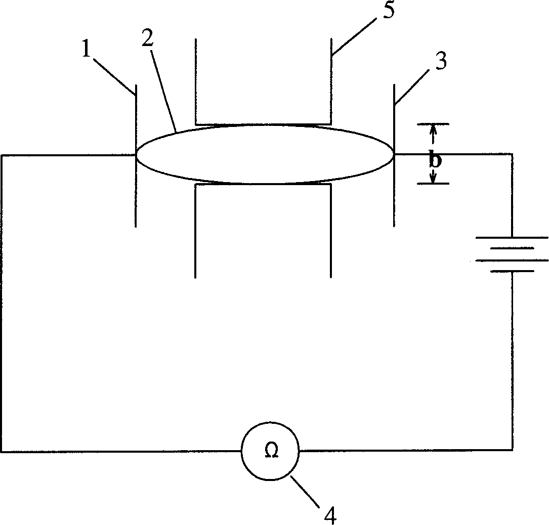
[0024] See figure 2 , The outer surface of the deformable medium 3 between the two electrode plates 1, 2 may be provided with a restricting piece 5, which in this embodiment is two restricting blocks 5, and the restricting block 5 is an insulator. The material selection and limitation of the deformable medium 3 are the same as those in Example 1, except that the measured displacement is the transverse direction between the two limiting blocks arranged between the two conductors 1 and 2 to limit the radial displacement of the deformable medium 3. distance b. The change of the lateral distance between the two limiting blocks 5 causes the cross-sectional area of ​​the deformable medium 3 resistor between the electrodes to change, which in turn causes the resistance value to change inversely proportional to the lateral distance, see the calculation formula of embodiment 1 (the present embodiment The lateral distance b may be the lateral distance S) in the formula. The measured ...


PUM


Abstract

The invention relates to a small displacement sensing method and apparatus, which relate to a measuring method and apparatus for displacement, temperature and strength.The invention sets deformation medium with some electrical resistance between two electric conductors, the bulk of which changes with the change of measured displacement, leading to the change of said deformation medium electric conductor. The required displacement parameter will be get through measuring the change of said deformation electric resistance between two electric conductors.

Description

technical field [0001] The invention relates to a method and device for measuring physical quantities such as displacement, temperature and strength, in particular to a small displacement sensing method and device. Background technique [0002] The existing displacement sensing methods mainly include the following types: 1. Metal wire film or patch is used. Although this method is mature and cheap, it can only measure the strain, so it is also called strain gauge. Usually the finished component size cannot be too small. 2. The thin film based on silicon material is used to measure the strain, and the silicon material itself needs a protective device. It can be made very small, but the cost is very high. 3. The optical fiber sensing method, which measures the strain through the optical change caused by the deformation of the material, requires a CCD imaging element, and the cost is also very high. 4. Resistance ruler, which is a very high-precision length measurement metho...

Claims


Application Information

Patent Timeline
Patent Type & Authority Patents(China)
IPC IPC(8): G01B7/16G01B7/02G01D5/16
CPCG01D5/16G01B7/16G01D5/183
Inventor 唐荣华
Owner 唐荣华
Why Eureka
Eureka Blog
Learn More