Method and device for realizing main backup of clock in synchronizing system

A synchronization system, master-backup technology, applied in the direction of synchronization devices, transmission systems, digital transmission systems, etc., can solve problems such as phase inconsistency, discontinuity, and devices that do not achieve hot switching

Inactive Publication Date: 2007-02-07
ZTE CORP
View PDF4 Cites 0 Cited by
  • Summary
  • Abstract
  • Description
  • Claims
  • Application Information

AI Technical Summary

Problems solved by technology

[0005] Due to reasons such as phase resolution and phase randomness, the phase difference between the active and standby clock boards may be any value within the half cycle of the voltage-controlled oscillator (VCO) output frequency. The phases of the main and standby clock boards are continuous, and the phases of the output clocks of the main and standby clock boards are inconsistent. For example, if a 16.384MHZ VCO is used in the program-controlled switch system, the phase difference between the output clocks of the main and standby clock boards is roughly between 0 and 30ns. If the main and standby clock boards are switched, There will be a change in the clock duty cycle of one clock cycle, so the phase discontinuity occurs. Even if the master-standby seamless switch can be achieved, that is, there is no time interval between the main output being turned off and the standby output being turned on, it cannot be prevented. The occurrence of the above-mentioned phase discontinuity causes delay in the implementation process of active / standby switchover
[0006] 2. Use the method of long and short pins to realize the main and standby switching. The disadvantage of this method is that it needs the cooperation of connectors;
Since the switchover can only be done through a single board, the active / standby selection can only be made through the operation of this board. If the board fails, the active / standby switchover cannot be completed. Therefore, the device does not achieve real hot switching

Method used


Image

  • Method and device for realizing main backup of clock in synchronizing system
  • Method and device for realizing main backup of clock in synchronizing system
  • Method and device for realizing main backup of clock in synchronizing system

Examples


Embodiment Construction

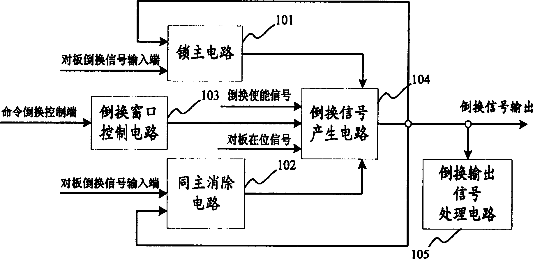
[0029] Such as figure 1 Shown is a functional block diagram of the main-standby switching circuit provided by the present invention. The main-standby switching device involved in the present invention uses a main-standby switching circuit including a lock main circuit 101, a same main cancellation circuit 102, and a switching window control circuit. 103. Inverted signal generating circuit 104 and inverted output signal processing circuit 105.

[0030] The lock main circuit 101 is used to lock the state of the main single board in the synchronization system. Once a board in the system is in the active state, unless there is a man-made control or a system failure causes an active / standby switchover, the board will always be active, which can prevent the system from causing active / standby oscillation due to interference;

[0031] The same main cancellation circuit 102 is used to avoid the situation that two single boards are simultaneously active. When two boards in the system are w...


PUM


Abstract

A device implementing the main and backup clock in synchronism system includes the circuit for reversing the main to the backup. The reversing circuit includes the circuit for locking the main, the circuit for removing the main, the circuit for generating the reversing signal, the reversed signal output processor. The invention can either avoid the state of which the two boards are as the main at same time, also can eliminate the phase oscillation at state of the main, meanwhile can reduce the time delay for reversing the main to the backup.

Description

Technical field [0001] The invention relates to a method and a device for switching between main and standby, in particular to a method and device for realizing main standby (hot backup) and hot switching of a synchronized clock in a synchronization system in the communication field. Background technique [0002] The main-standby redundancy design has been widely used in communication system equipment, especially the hot backup function it realizes has greatly improved the reliability and stability of the equipment. In a synchronization system in the communication field, all single boards or sub-systems work under their synchronized clocks. Therefore, as the core of the synchronization system, the reliability of the clock board is particularly important. Therefore, the clock board must be switched between active and standby. [0003] At present, in the synchronization system, the devices and methods for realizing clock master / slave switching are roughly in the ...

Claims


Application Information

Patent Timeline
Patent Type & Authority Patents(China)
IPC IPC(8): H04L7/02H04B1/74H03K19/00
Inventor 刘培章陈颖川李光年王承忠
Owner ZTE CORP
Why Eureka
Try Eureka