

Tech, for producing sebific duct of silicon rubber and special mould core thereof
A production process, silicone rubber technology, applied in the field of new silicone rubber hose production process, can solve the problems of difficult demoulding, easy extrusion and fracture of the reinforcement layer, etc., and achieve the effect of easy demoulding, smooth inner wall and high adhesion strength
- Summary
- Abstract
- Description
- Claims
- Application Information
AI Technical Summary
Problems solved by technology
Method used
Image

Examples
Embodiment Construction
[0022] The embodiment of the present invention is characterized in that the process steps are as follows:
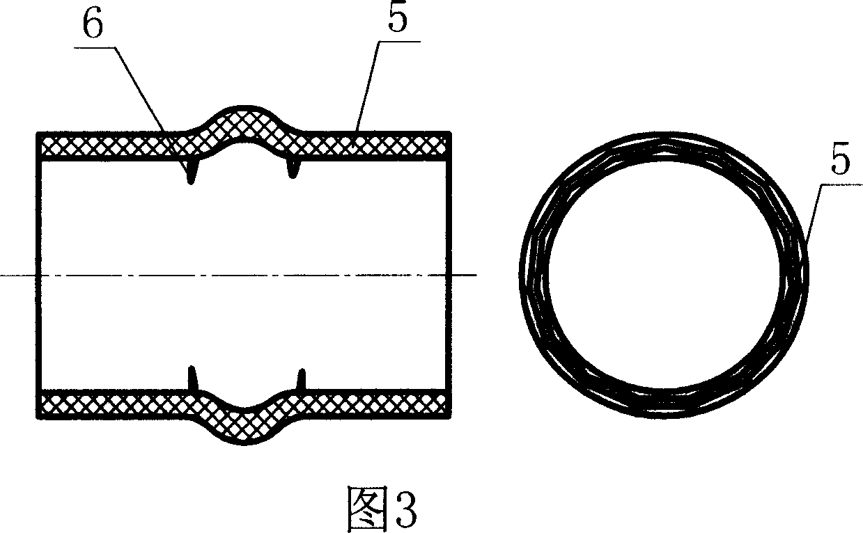
[0023] a. directly forming the rubber hose blank on the surface of the capsule 7 compatible with the inner diameter of the rubber hose 11;
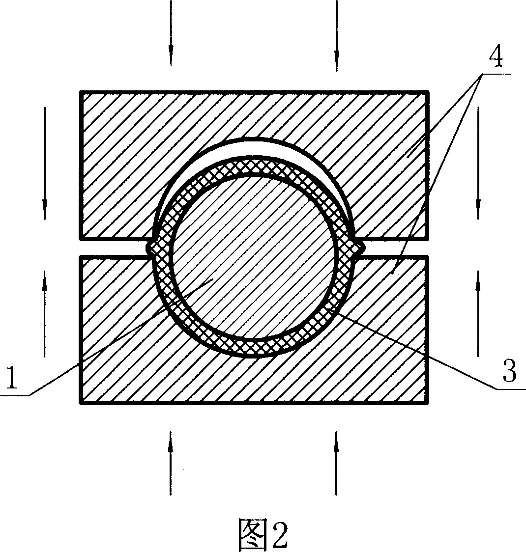
[0024] b. put the formed rubber tube blank 9 together with the capsule into the cavity of the mold 10;
[0025] c. Close the mold, inject internal pressure into the capsule, and vulcanize;
[0026] d. After the vulcanization is completed, release the pressure, pull out the capsule, and obtain the rubber hose.
[0027] Since the rubber hose has certain shrinkage during the preparation process, the outer diameter of the capsule should be slightly smaller than the inner diameter of the rubber hose.
[0028] The end of the capsule in step a is provided with an internal pressure connecting pipe 8. During specific implementation, the internal pressure connecting pipe can be set on the end of the capsule before or after forming the rubbe...
PUM
 Abstract
Description
Claims
Application Information