
Plastic light guide fiber end face processing method

一种光导纤维、加工方法的技术,应用在光导、光波导的耦合、光学等方向,能够解决不能形成等问题,达到容易操作、简便端面加工、加工结构简单的效果

Inactive Publication Date: 2007-03-28
NHK SALES
View PDF8 Cites 0 Cited by
  • Summary
  • Abstract
  • Description
  • Claims
  • Application Information

AI Technical Summary

Problems solved by technology

[0006] However, the above-mentioned conventional processing apparatus for processing the end face of an optical fiber by heating can be applied to the formation of a convex hemispherical surface, and there is a problem that other shapes including a concave hemispherical surface cannot be formed.

Method used


Image

  • Plastic light guide fiber end face processing method
  • Plastic light guide fiber end face processing method
  • Plastic light guide fiber end face processing method

Examples


Embodiment Construction

[0067] Hereinafter, embodiments of the present invention will be described in detail with reference to the drawings. The processing method of the plastic optical fiber end face of the present invention is to use a semicircular cutting blade to cut at least the core part of the plastic optical fiber end face into a hemispherical surface in the through hole of the jig, and the semicircular cutting blade is convex or concave. Shaped semicircular, the end face of the plastic optical fiber is machined into a convex or concave hemispherical surface.

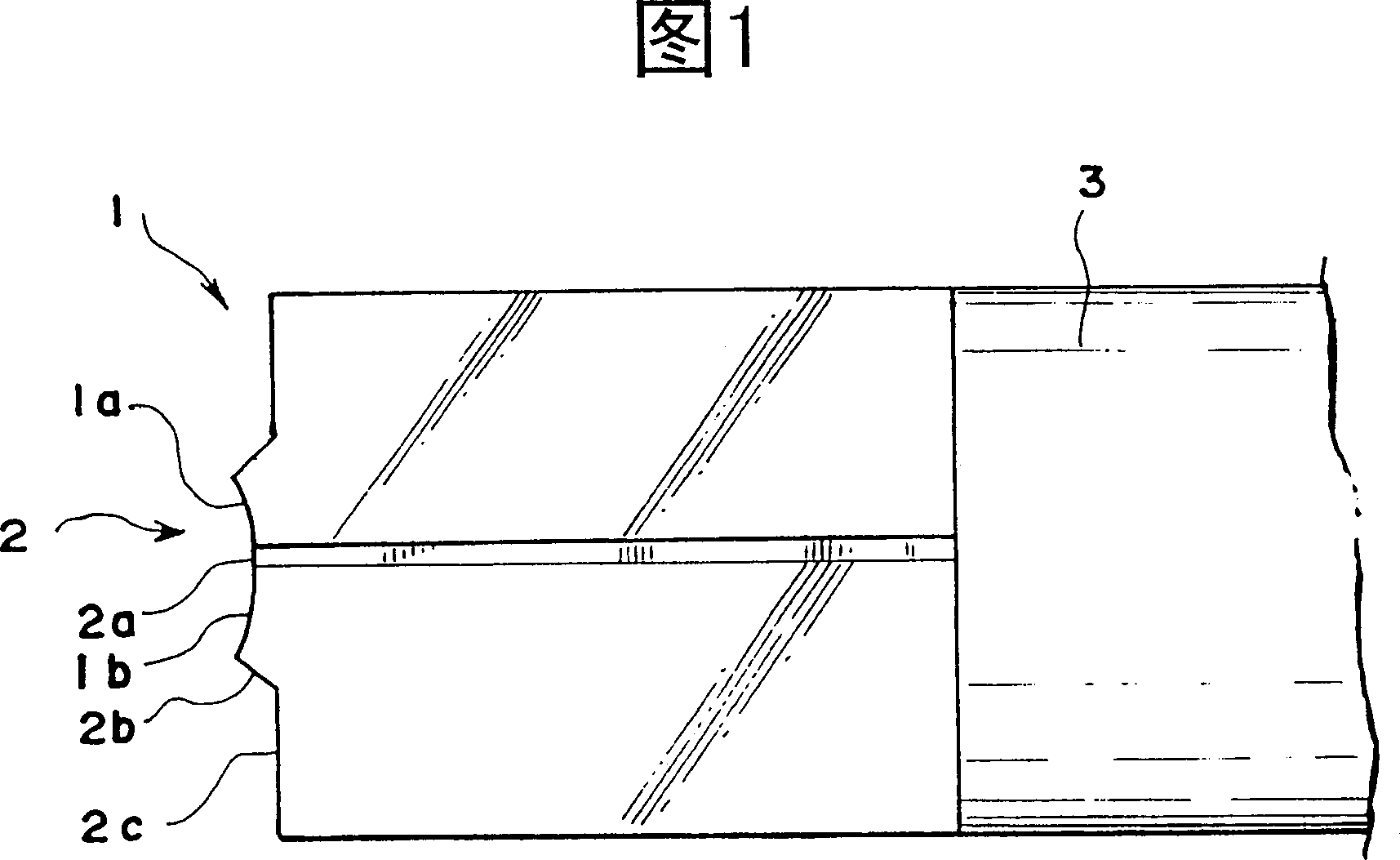
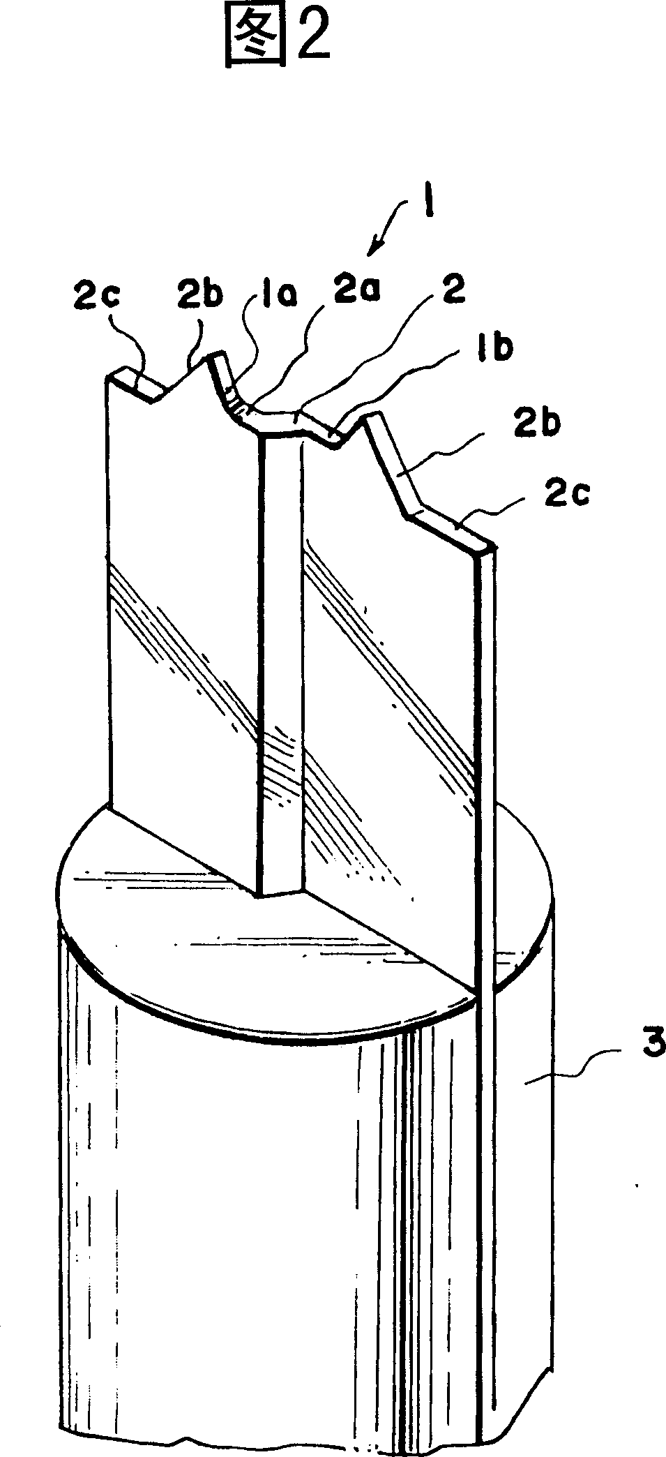
[0068] 1 and 2 are an enlarged front view and an enlarged perspective view of main parts showing an example of a semicircular cutting edge. In the above figure, the cutting edge 1 is provided at the tip of the shaft portion (cylindrical portion) 3. In this embodiment, the cutting edge 1 is formed into a convex semicircular shape by two cutting edges 1a, 1b. Specifically, as shown in FIGS. 1 and 2, the cutting edge 1 has a head 2 forme...


PUM


Abstract

A plastic optical fiber end surface processing method, a processing apparatus for the method, a cutter for use in the method, and a plastic optical fiber connecting method are provided. The processing method is that at least the core part of the end face of the plastic optical fiber is cut to be formed into a hemisphere face with a half circular cutting blade. The processing apparatus includes: a motor; a cutting blade connected with connecting component or directly to the driving shaft of the motor; a holder having a through hole for inserting the cutting blade into the middle portion of the through hole; a cutter inserted from one side into the through-hole of the holder for cutting at least the core part of the end face of the plastic optical fiber with rotating cutting blade. The invention is capable of processing the plastic optical fiber to be not only convex semi-spherical surface but also concave semi-spherical surface and arbitrary profile according to the change of the cutting blade shape.

Description

technical field [0001] The present invention relates to a method for processing the end face of a plastic optical fiber, which is a processing method for processing the end face of a plastic optical fiber into a convex or concave hemispherical surface (hereinafter referred to simply as an optical fiber), As well as its processing device, the connection between the cutting blade and the optical fiber, the connection between the optical fiber and the machine, and the connection between the optical fiber and the connection device such as the connector, etc., especially involving the loss of light on the connecting part. Connection method with few optical fibers. Background technique [0002] In the past, the method of processing the end surface of the optical fiber into a hemispherical surface was usually a method of processing the end surface after heating. For example, there is a method of keeping the optical fiber in a vertical state, heating its tip with a high-temperature...

Claims


Application Information

Patent Timeline
Patent Type & Authority Patents(China)
IPC IPC(8): G02B6/25G02B6/00G02B6/255G02B6/38G02B6/42
CPCG02B6/2555G02B6/25G02B6/2551G02B6/4203G02B6/262G02B6/00
Inventor 饭岛良美木造弘
Owner NHK SALES
Learn More