Exhaust gas treating tower

A waste gas treatment tower, waste gas technology, applied in the separation of dispersed particles, chemical instruments and methods, use of liquid separation agents, etc., can solve the problems of different flow rates, uneven flow of waste gas, etc., to improve flow rate, contact efficiency, and performance. Effect

Inactive Publication Date: 2007-04-04
MITSUBISHI HITACHIPOWER SYST LTD
View PDF5 Cites 0 Cited by
  • Summary
  • Abstract
  • Description
  • Claims
  • Application Information

AI Technical Summary

Problems solved by technology

[0013] However, in the exhaust gas treatment tower 1, the flow direction of the exhaust gas is not uniform, and an abnormal flow direction is formed due to various reasons, and the flow velocity also varies with the location.

Method used


Image

  • Exhaust gas treating tower
  • Exhaust gas treating tower
  • Exhaust gas treating tower

Examples


no. 1 approach

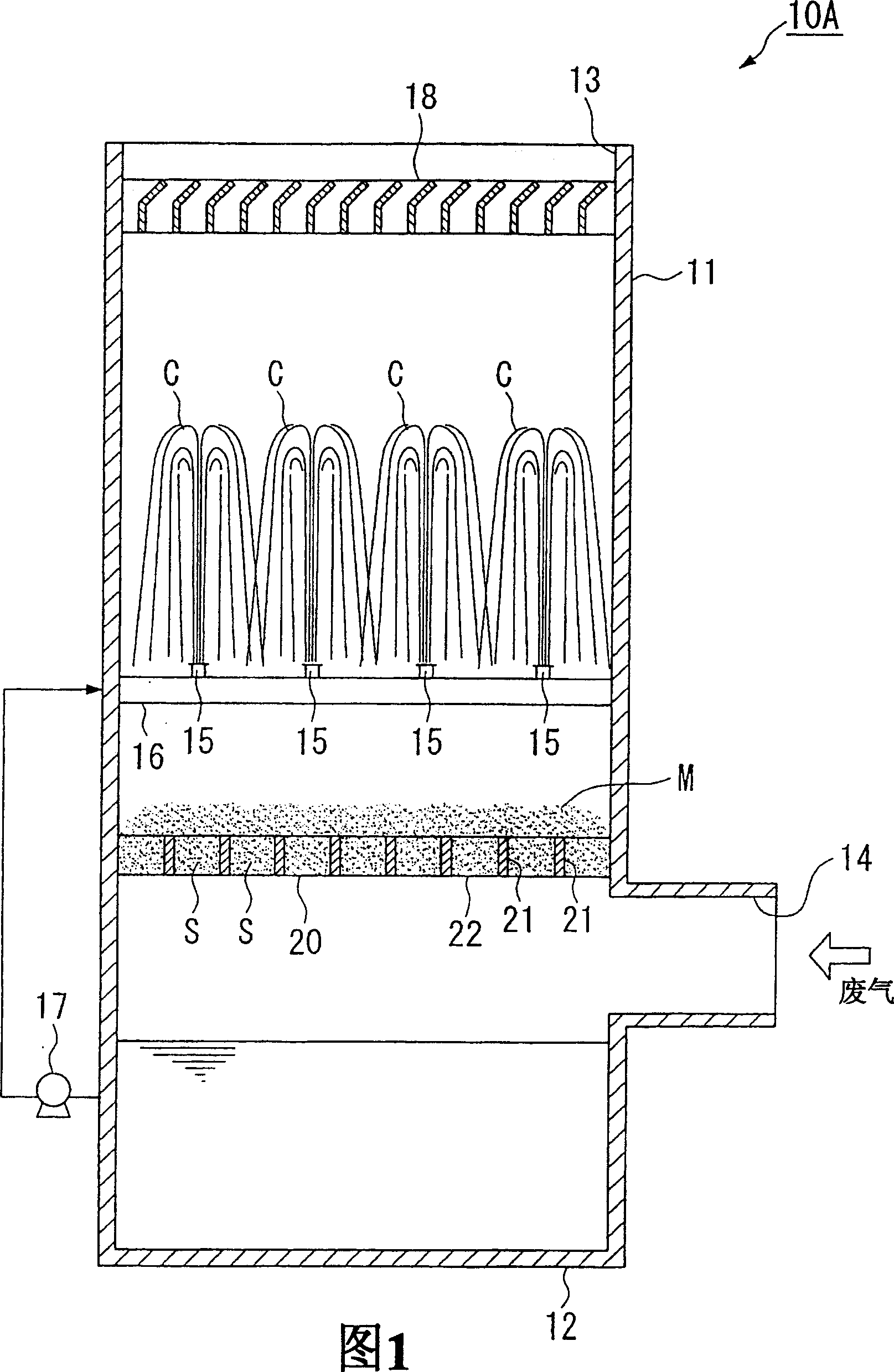
[0069] FIG. 1 is a cross-sectional view illustrating the configuration of an exhaust gas treatment tower 10A in the present embodiment.

[0070] As shown in FIG. 1 , in the exhaust gas treatment tower 10A, the tower main body 11 is, for example, a cylindrical shape with a rectangular cross section, the bottom of which is closed by a bottom plate 12 , and an opening 13 is formed in the upper part. In addition, an introduction port 14 is formed at the lower side of the tower main body 11 to introduce exhaust gas into the tower main body 11 .

[0071] A pipe 16 including a plurality of nozzles 15 is provided in the tower main body 11 . The liquid accumulated at the bottom of the tower main body 11 is sucked up by the pump 17 and supplied to the pipe 16 . The nozzles 15 eject the liquid upward in a columnar shape, and these nozzles 15 are arranged at an appropriately set interval so that a gap is formed between the liquid columns C ejected upward from the nozzles 15 adjacent to e...

no. 2 approach

[0084] Next, an example of the case where the spray nozzle (nozzle) 30 is added to the exhaust gas treatment tower 10B will be shown. In addition, since the basic configuration of the exhaust gas treatment tower 10B is the same as that of the above-mentioned first embodiment, the same reference numerals are used, and the description thereof will be omitted.

[0085] As shown in FIG. 5 , a pipe 31 including a plurality of spray nozzles 30 is provided in a portion below the nozzle 15 and above the inlet 14 of the tower main body 11 of the exhaust gas treatment tower 10B.

[0086] A booster pump (pump) 33 is connected to the piping 31 to boost the pressure of the liquid sucked up from the bottom of the column main body 11 by the pump 17 . Moreover, it is also possible to form the following structure: the pump 17 and the booster pump 33 are not equipped in two stages, and the liquid is directly sucked up from the bottom of the tower main body 11 by the booster pump 33, but in this...

no. 3 approach

[0095] Next, an example of a case where both the droplet generation member 20 and the spray nozzle 30 are combined and installed in the exhaust gas treatment tower 10C will be shown. Furthermore, since the basic configuration of the exhaust gas treatment tower 10C is the same as that of the above-mentioned first and second embodiments, the same reference numerals are used, and description thereof will be omitted.

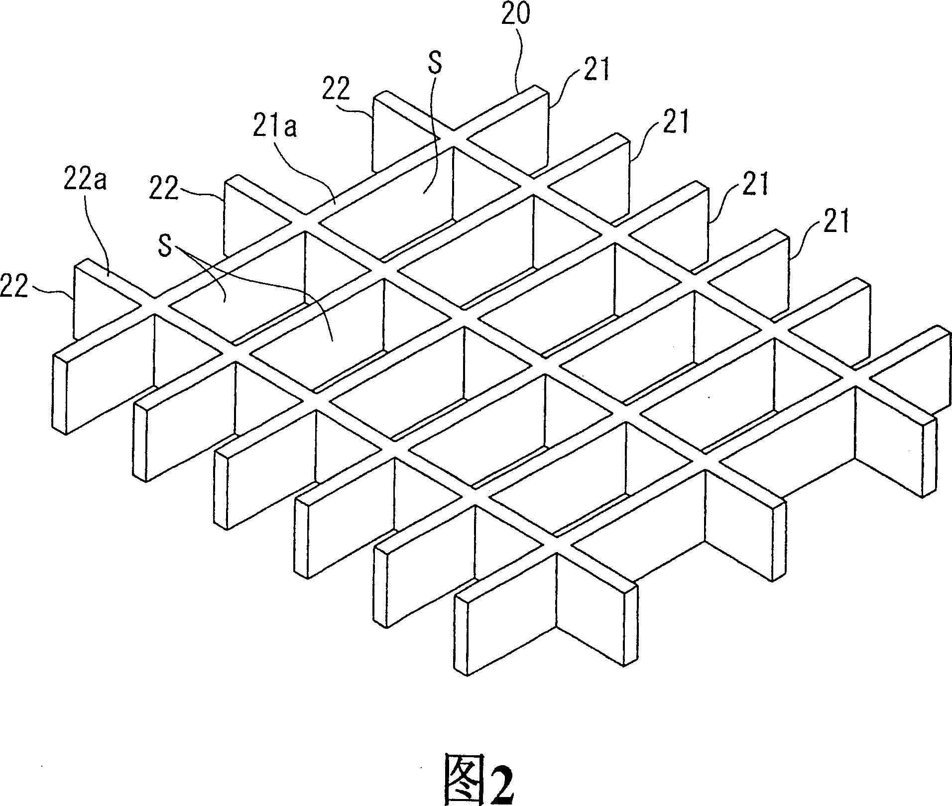
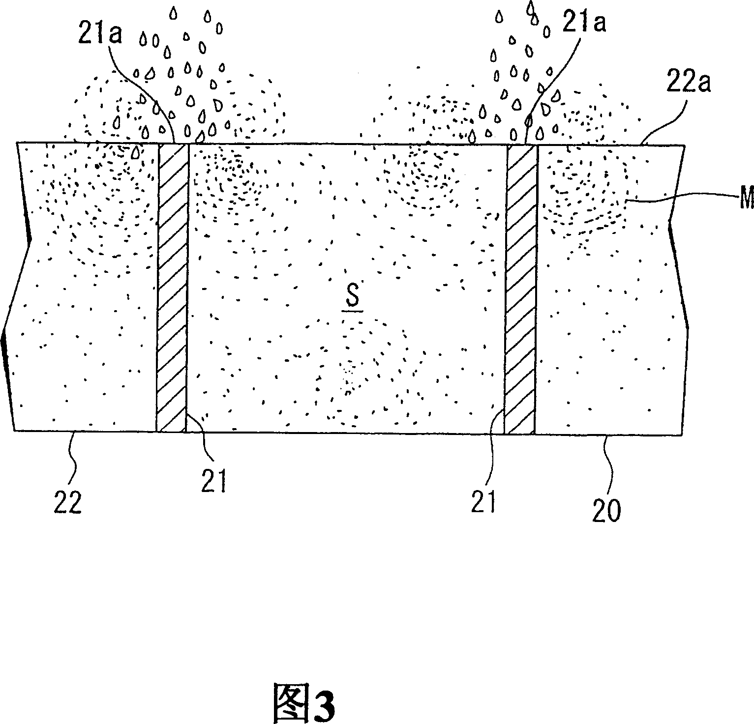
[0096] As shown in FIG. 7 , a pipe 31 provided with a plurality of spray nozzles 30 is provided in a portion below the nozzle 15 and above the inlet 14 of the tower main body 11 of the exhaust gas treatment tower 10C. Furthermore, the droplet generation member 20 is provided in a portion below the spray nozzle 30 of the exhaust gas treatment tower 10C and above the introduction port 14 .

[0097] In this configuration, the liquid sprayed upward from the nozzle 15 forms a liquid column C and falls downward. Then, the falling liquid collides with the upper surfaces 2...


PUM

PropertyMeasurementUnit
densityaaaaaaaaaa

Abstract

Provided is an exhaust gas treating tower in which exhaust gas flow velocity is increased more than a prior art case so that exhaust gas treating efficiency can be enhanced or the exhaust gas treating tower can be made compact if equivalent performance is to be maintained. Also, an exhaust gas treating tower ensuring a liquid recovery is provided. In an exhaust gas treating tower 10A, liquid columns C are generated and also a liquid drop generating member 20 is provided to thereby generate liquid drops M therearound to be floated. Also, liquid is spouted from spray nozzles to thereby generate liquid films F in area different from the liquid columns C. In an exhaust gas treating tower 110, a liquid drop eliminator 120 is provided upstream of a mist eliminator 118. Interval P1 of collecting plates 121 of the liquid drop eliminator 120 is made larger than interval P2 of collecting plates 119 of the mist eliminator 118. Thereby, liquid drops having larger particle diameter contained in the exhaust gas are collected by the liquid drop eliminator 120.

Description

technical field [0001] The present invention relates to an exhaust gas treatment tower installed in various equipment, boilers, and the like. Background technique [0002] In order to remove sulfur oxides (SO 2 ), an exhaust gas treatment tower that adopts a gas-liquid contact method. [0003] As this exhaust gas treatment tower, there is a so-called liquid column type treatment tower, which sprays the absorbing liquid of sulfur oxides upward in a column shape (for example, refer to Patent Document 1). As shown in FIG. 31 or FIG. 32, in this liquid column type exhaust gas treatment tower 1, the exhaust gas is introduced from the inlet 2 formed on the lower side, and is discharged in a columnar shape while the exhaust gas flows to the upper discharge port 3. Contact with the liquid column C, so that the sulfur oxides contained in the exhaust gas are removed. [0004] In such a liquid column type exhaust gas treatment tower 1, the exhaust gas that comes into contact with th...

Claims


Application Information

Patent Timeline
Patent Type & Authority Patents(China)
IPC IPC(8): B01D53/78B01D47/14B01D53/18
CPCB01D47/063B01D53/78
Inventor 冈田健一高品彻冲野进神山直行中村积本城新太郎高野幸造大石刚司岩下浩一朗
Owner MITSUBISHI HITACHIPOWER SYST LTD
Why Eureka
Try Eureka