Combined DC/DC booster converter

A DC boost and converter technology, which is applied in the direction of conversion equipment without intermediate conversion to AC, can solve the problems of high working voltage and poor stability of power devices

Inactive Publication Date: 2007-05-09
王玉富 +2
View PDF2 Cites 1 Cited by
  • Summary
  • Abstract
  • Description
  • Claims
  • Application Information

AI Technical Summary

Problems solved by technology

[0006] The above analysis shows that when the duty cycle is close to 0.9, the stability of the two circuits becomes very poor, and the operating voltage of the power device is high, especially the Cuk circuit

Method used


Image

  • Combined DC/DC booster converter
  • Combined DC/DC booster converter
  • Combined DC/DC booster converter

Examples


Embodiment Construction

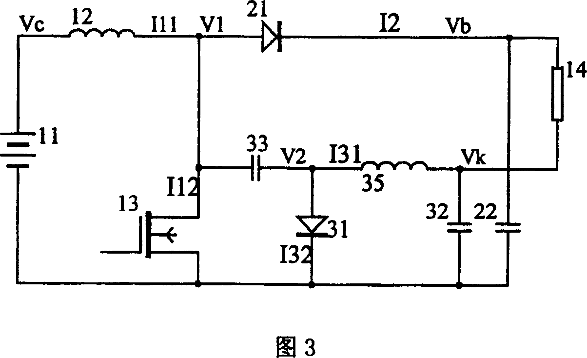
[0017] The combined DC-DC boost converter proposed by the present invention has a circuit as shown in Figure 3, including:

[0018] (1) It is used to provide a shared main boost inductor 12 and a switch tube 13 for the Boost circuit and the Cuk circuit, wherein the positive pole of the input power supply 11 of the converter is connected to one end of the main boost inductor 12, and the other end of the main boost inductor 12 One end is connected to the drain of the switch tube 13, the source of the switch tube 13 is connected to the negative pole of the converter input power supply 11, and the connection between the main boost inductor 12 and the drain of the switch tube 13 is the main driving point of the converter circuit V1;

[0019] (2) For boosting the voltage of the main driving point V1 of the converter circuit forward and storing energy, to generate the Boost circuit of the voltage of the positive pole Vb of the converter output power supply, composed of a switching di...


PUM


Abstract

This invention relates to a combination type DC-DC boosting inverter. It is characterized by: (1). an inductor and a switching tube are used for supplying shared main boostnig for Boost circuit and Cuk circuit; (2) Boost circuit is used for proceeding positive boosting and energy-storage for the voltage of main driving point of inverter circuit, to produce positive pole point voltage for output power source of inverter; (3) Cuk circuit is used for proceeding negative boosting and energy-storage for the voltage of main driving point of inverter circuit, to produce negative pole point of output power source of inverter. This invented voltage boosting inverter is of simple circuit. Under the driving of the booster made of main inductor and switching tube, the Boost unit gives voltage gain, while the CUk unit gives-out voltage gain. The coefficient of stability W=0.0095, one fold increased.

Description

technical field [0001] The present invention relates to a combined DC-DC boost converter, especially a boost converter combining a basic boost converter (hereinafter referred to as Boost circuit) and a capacitive isolation buck-boost converter (hereinafter referred to as Cuk circuit) , belonging to the technical field of DC conversion. technical background [0002] Boost converter Boost circuit is the most basic and commonly used boost circuit. When its duty cycle is close to 0.9, the boost gain of the circuit increases rapidly, which makes it difficult to guarantee the working stability and power conversion efficiency of the circuit. should be avoided. The Cuk circuit has a buck-boost function, and the output ripple is small. However, as a boost circuit, the gain is smaller than that of the Boost circuit. When the duty cycle is close to 0.9, the stability and power conversion efficiency of the circuit are also difficult to guarantee. US Patent No. 6,522,192 discloses a vo...

Claims


Application Information

Patent Timeline
Patent Type & Authority Patents(China)
IPC IPC(8): H02M3/04
Inventor 王玉富马兴凯陶晓蜂
Owner 王玉富
Why Eureka
Try Eureka