Method of connecting heat conduit and radiation fin

A technology of heat dissipation fins and heat dissipation fin groups, which is applied in semiconductor devices, indirect heat exchangers, lighting and heating equipment, etc., and can solve problems such as thermal resistance of heat pipes and heat dissipation fins

Inactive Publication Date: 2007-05-30
HONG FU JIN PRECISION IND (SHENZHEN) CO LTD +1
View PDF4 Cites 0 Cited by
  • Summary
  • Abstract
  • Description
  • Claims
  • Application Information

AI Technical Summary

Problems solved by technology

[0007] The combination method of the heat pipe and the heat dissipation fins of the present invention adopts friction welding of the heat dissipation fins to the heat pipe. Since the heat pipe and the heat dissipation fins are integrated through metal welding, no gap is formed between the two, which solves the problem of heat pipes and heat dissipation fins in the prior art. The problem of thermal resistance caused by the gap between the heat dissipation fins, and the heat sink made by the method provided by the present invention is also suitable for rapid mass production

Method used


Image

  • Method of connecting heat conduit and radiation fin
  • Method of connecting heat conduit and radiation fin
  • Method of connecting heat conduit and radiation fin

Examples


Embodiment Construction

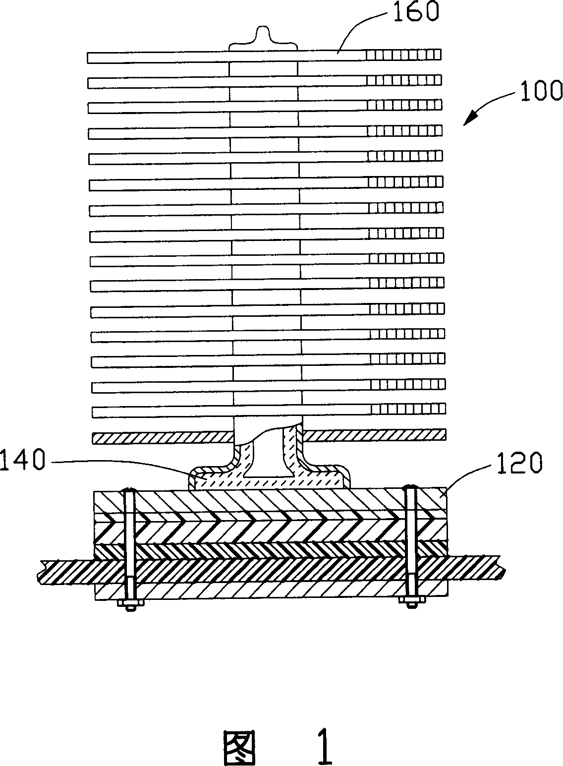
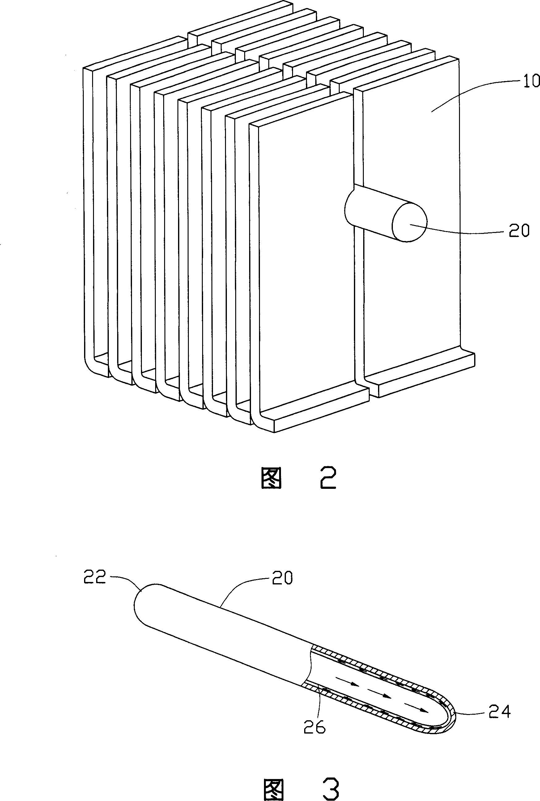
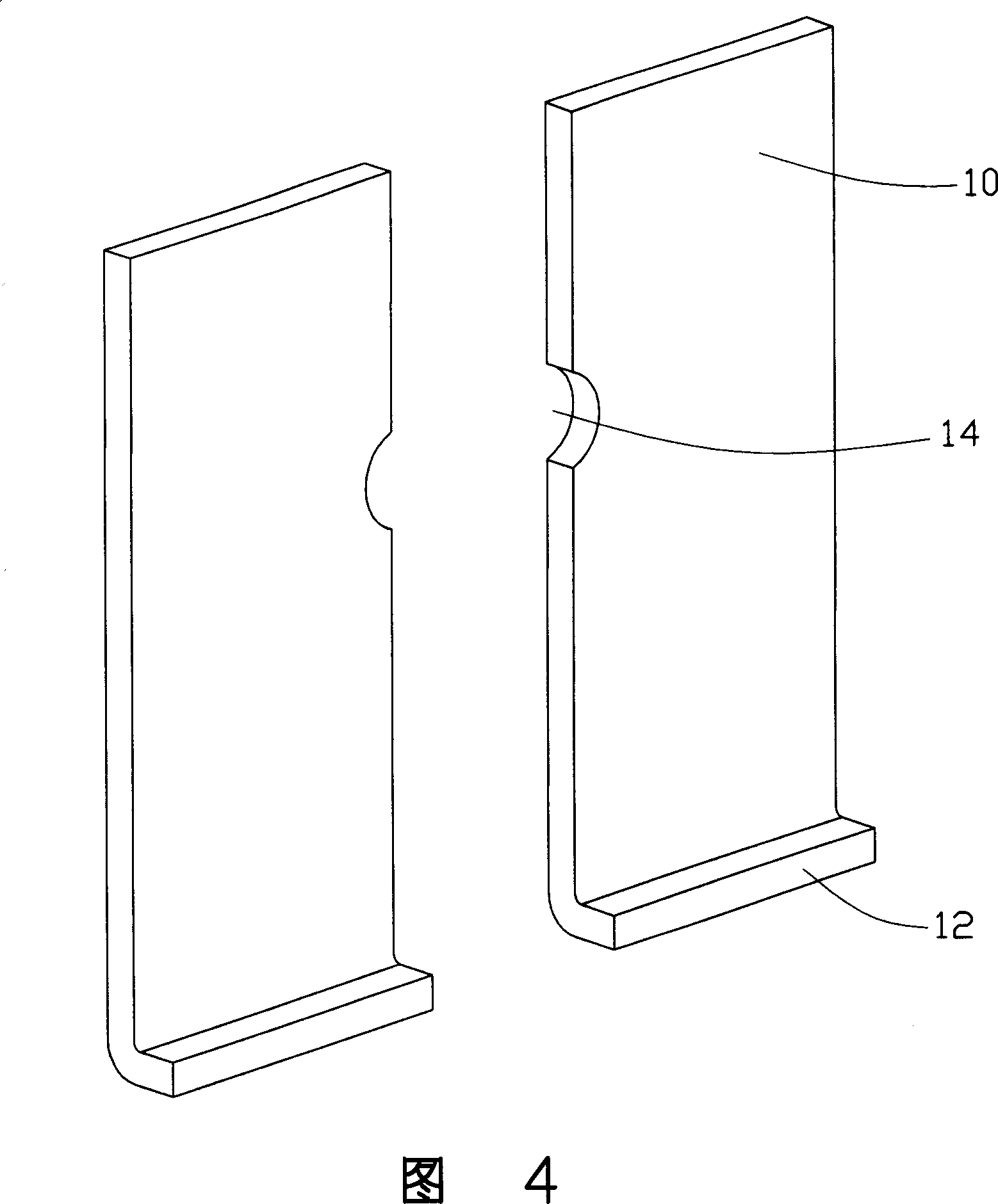
[0014] The method for combining the heat pipe and the heat dissipation fins of the present invention is applied to fast and tightly connecting the heat dissipation fins to the heat pipe. As shown in FIG. 2 , the present invention takes the connection of the heat pipe 20 and the heat dissipation fin 10 as a specific implementation mode to describe the present invention.

[0015] As shown in Figure 3, the heat pipe 20 has a pipe body, and first and second sealing ends 22, 24, wherein the inner wall of the pipe is provided with a capillary structure 26, and is filled with a working material for gas-liquid two-phase change. Fluid, the working fluid is preferably water or acetone; the capillary structure 26 can provide the power to return the working fluid that is in liquid state after releasing heat and cooling, and can also guide the fluid that is in gaseous state after absorbing heat and evaporating. , wire mesh type and sintered type are preferred; after filling the working flu...


PUM


Abstract

A jointing method of heat conduct pipe and radiating fin. A open is on the radiating fin then rotating the heat conduct pipe, and the radiating fin paralleled move to the conduct pipe; when the open contacts the heat conduct pipe, holding the heat conduct pipe rotating, and generating friction between the heat conduct pipe and the radiating fin the heat created by friction make the frictional surface as plastic melting state; and the heat conduct pipe and the open of the joined by pressure.

Description

【Technical field】 [0001] The invention relates to a combination method of heat pipes and heat dissipation fins, in particular to a combination method for eliminating the joint gap between heat pipes and heat dissipation fins. 【Background technique】 [0002] The computer has become an indispensable tool in many industries. With the continuous improvement of its demand, the computer industry has developed rapidly and by leaps and bounds. The performance of the computer depends largely on the central processing unit, whose speed and stability directly affect the performance of the whole machine. Performance, the higher the integration of the central processing unit and the faster the running speed, the greater the heat generated with it. If the heat is not dissipated in time, the heat will accumulate and the temperature will rise, which will greatly affect the stability of its operation. , Therefore, the heat generated by the central processing unit must be removed in time. ...

Claims


Application Information

Patent Timeline
Patent Type & Authority Patents(China)
IPC IPC(8): H01L23/34H01L23/427G06F1/20F28D15/00
Inventor 简士哲
Owner HONG FU JIN PRECISION IND (SHENZHEN) CO LTD
Why Eureka
Try Eureka