Communication terminal device and channel estimating method

A technology for channel estimation and communication terminals, which is applied in channel estimation, wireless communication, multiplexing communication, etc., and can solve problems such as inability to average channel estimation values, reduced reliability of channel estimation values, discontinuous time slots received by communication terminals, etc.

Inactive Publication Date: 2001-10-31
PANASONIC CORP
View PDF0 Cites 22 Cited by
  • Summary
  • Abstract
  • Description
  • Claims
  • Application Information

AI Technical Summary

Problems solved by technology

[0021] However, if the phase rotation of individual channel signals is properly performed slot by slot at the base station side, the receiving slots in the communication terminal are discontinuous, so the above-mentioned conventional communication terminal has the following problem: the channel cannot be adjusted within a range of multiple slots. estimates are averaged, the channel estimate is less reliable compared to the case where transmit diversity is not used

Method used


Image

  • Communication terminal device and channel estimating method
  • Communication terminal device and channel estimating method
  • Communication terminal device and channel estimating method

Examples


Embodiment 1

[0047] In Embodiment 1, the case where the dedicated channel signal A and the dedicated channel signal B are transmitted without changing the amplitudes in the base station will be described.

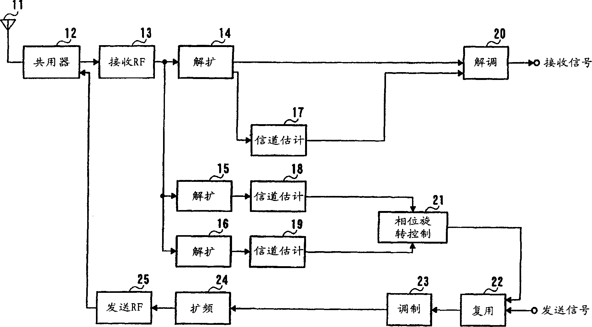
[0048] Figure 5 It is a structural block diagram of the communication terminal according to Embodiment 1 of the present invention.

[0049] exist Figure 5 In the communication terminal shown, antenna 201 receives a signal transmitted from a base station, and transmits a signal to the base station. The duplexer 202 switches the time zone of transmission and reception. The reception RF unit 203 amplifies the reception signal passed through the duplexer 202, and converts the frequency into a baseband signal.

[0050] The despreading section 204 despreads the output signal of the receiving RF section 203 using the spreading code of the dedicated channel signal, and extracts the modulated signal of the dedicated channel signal. Similarly, the despreading unit 205 despreads the output s...

Embodiment 2

[0086] In Embodiment 2, a case where the amplitudes of the dedicated channel signal A and the dedicated channel signal B are changed and transmitted in the base station will be described.

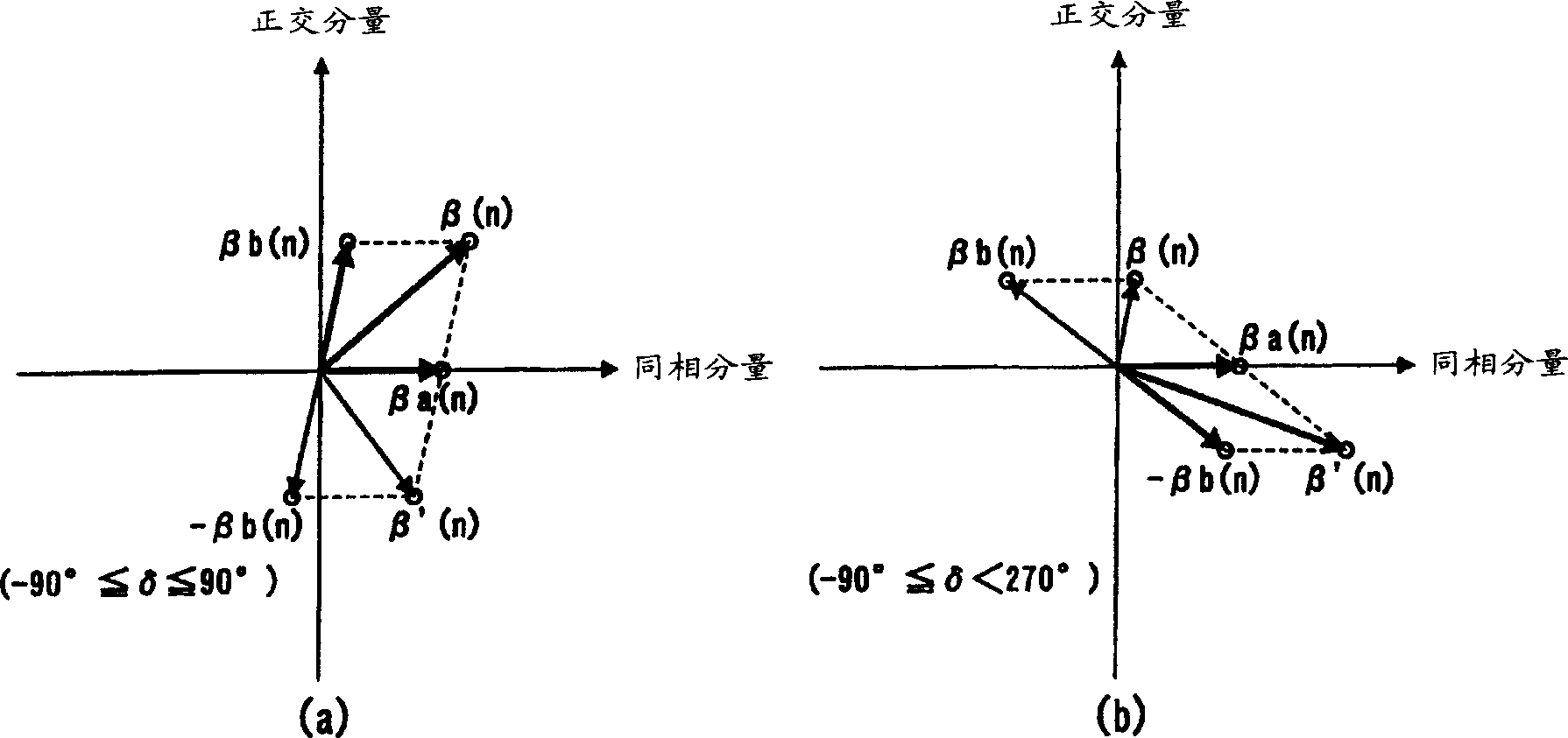
[0087] Below, use Figure 7 The relationship between the channel estimation values ​​in this embodiment will be described.

[0088] In the case where the amplitude of the individual channel signal B is set to be a times that of the individual channel signal A in the base station (hereinafter, this a is referred to as "amplitude coefficient"), if the amplitude ratio of αa(n) to βa(n) is k, then the amplitude ratio of αb(n) to βb(n) is (k×a).

[0089] In this case, if Figure 7 As shown, the channel estimated value β(n) of the individual channel signal and the combined value α(n) of the channel estimated values ​​of the common pilot channel signal A and the common pilot channel signal B do not face the same direction.

[0090]Therefore, when the base station transmits the dedicated channel...

Embodiment 3

[0102] When the maximum Doppler frequency of fading is low and the fading changes slowly, the reliability of the channel estimation value can be improved by averaging the fading estimation values ​​within a range of multiple receiving time slots.

[0103] However, as described above, when transmitting diversity is introduced into a wireless communication system, since the receiving slots are not consecutive, channel estimation values ​​cannot be averaged over a plurality of slots.

[0104] Embodiment 3 is used to solve this problem, and describes the case where transmit diversity is introduced and channel estimation values ​​are synthesized within a range of multiple time slots.

[0105] Figure 9 is a structural block diagram of a communication terminal according to Embodiment 3 of the present invention. exist Figure 9 In the communication terminal shown, for the Figure 5 The same components of the communication terminal shown are appended with Figure 5 The same refere...


PUM


Abstract

Phase rotation amount estimation section 210 rotates a channel estimation value of the common pilot channel B signal by a candidate amount of phase rotation [theta] ([theta]=0, 180) and synthesizes the rotated channel estimation value and the channel estimation value of the common pilot channel A signal. Then, phase rotation amount estimation section estimates an amount of phase rotation having this synthesis result most orthogonal to the channel estimation value of the individual channel signal as the amount of phase rotation. Channel estimation value synthesis section 211 synthesizes a value obtained by rotating the channel estimation value of the common pilot channel B signal by an amount of phase rotation [theta] and the channel estimation value of the common pilot channel A signal. This allows a radio communication system using transmission diversity to improve the reliability of channel estimation values.

Description

technical field [0001] The present invention relates to a CDMA system communication terminal device and a channel estimation method used in a wireless communication system such as a car phone or a mobile phone. Background technique [0002] In wireless communication systems, transmit diversity is sometimes used, that is, in order to increase the reception power of individual channel transmission signals (hereinafter referred to as "individual channel signals") at the communication terminal at the base station side, a plurality of diversity antennas are transmitted to one communication terminal. The terminal sends individual channel signals. [0003] figure 1 An example of a wireless communication system using transmit diversity is the system disclosed in 3GPP WG1 TSG-RANWG1 R1-99832 (Physical channels and mapping of transport channels onto physical channels (FDD)) system structure diagram. [0004] Such as figure 1 As shown, base station 1 transmits common pilot channel ...

Claims


Application Information

Patent Timeline
Patent Type & Authority Applications(China)
IPC IPC(8): H01Q3/24H04B1/712H04B7/06H04B7/08H04B7/26H04J13/00H04L25/02H04L27/00H04W16/28
CPCH04B7/06H04L2027/0022H04B7/0615H04L25/0214H04L25/0204H04B7/02
Inventor 平松胜彦
Owner PANASONIC CORP
Why Eureka
Try Eureka