Projector with reflective LCD element

A technology for liquid crystal elements and projection devices, applied in projection devices, optical elements, optics, etc., can solve problems such as not being proposed

Inactive Publication Date: 2007-06-06
VICTOR CO OF JAPAN LTD
View PDF13 Cites 0 Cited by
  • Summary
  • Abstract
  • Description
  • Claims
  • Application Information

AI Technical Summary

Problems solved by technology

It is not proposed that without using PBS, a contrast ratio of more than 500:1 can be obtained, and interference fringes and uneven left and right are hardly generated, and a projection device using a reflective liquid crystal element

Method used


Image

  • Projector with reflective LCD element
  • Projector with reflective LCD element
  • Projector with reflective LCD element

Examples


Embodiment Construction

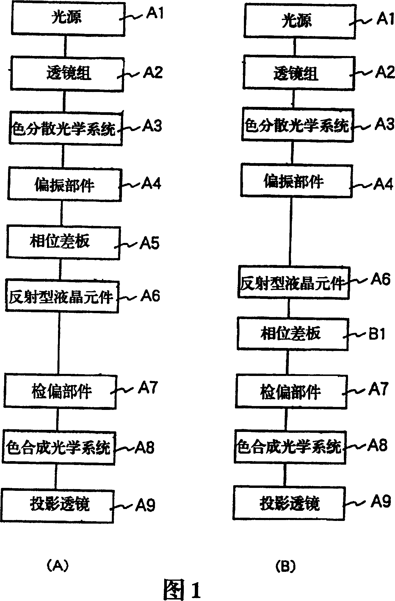
[0094] Hereinafter, a projection device using a reflective liquid crystal element according to an embodiment of the present invention will be described with reference to the drawings. FIG. 1(A) is a block diagram of a first embodiment of a projection apparatus using a reflective liquid crystal element according to an embodiment of the present invention, and FIG. 1(B) is a block diagram showing a projection apparatus using a reflective liquid crystal element according to an embodiment of the present invention. A block diagram of the second embodiment. In Fig. 1(A), the light emitted from the light source A1 passes through the lens group A2, passes through the color separation optical system A3 for color separation of the RGB three primary color lights, and after being color separated, passes through the polarizing component A4 and the phase difference plate respectively A5 is incident on the reflective liquid crystal element A6 in which a liquid crystal layer is interposed betw...


PUM

PropertyMeasurementUnit
angleaaaaaaaaaa
angleaaaaaaaaaa

Abstract

To solve problems associated with contrast which is not so heightened as expected and of which the difference among positions on a projection screen is large in using a vertical alignment reflective liquid crystal element which usually accompanies high contrast, in an optical system constructed so as to divide an optical path before a color separation and combination system. Light modulated by the reflective liquid crystal element A6 corresponding to image data is made incident on an analyzer A7 arranged in relation of a crossed Nichol to a polarizer A4 and is analyzed. When a liquid crystal layer of the reflective liquid crystal element A6 is driven and turned on with the image data to be displayed, the analyzer A7 transmits the incident light and when the liquid crystal layer is not driven and is in a turned-off state, the analyzer A7 absorbs the incident light and does not transmit the incident light. An optical retardation plate A5 is uniaxially anisotropic and has an optic axis inclined in a direction oblique to the film surface and the optic axis is set to perpendicularly intersect a transmission axis of the polarizer A4 neighboring the optical retardation plate A5. Thereby a bright optical system is realized at a low cost without using a PBS(polarization beam splitter).

Description

technical field [0001] The present invention relates to a projection device using a reflective liquid crystal element, and more particularly to a projection device using a reflective liquid crystal element for displaying a large image by using a color separation / color synthesis unit, a reflective liquid crystal panel, and the like. Background technique [0002] In recent years, research on a reflective liquid crystal panel in which a reflective electrode is provided in each pixel to increase the numerical aperture of the pixel has been actively carried out, and projection-type liquid crystal projectors using this reflective liquid crystal panel have been released. Compared with the conventional transmissive liquid crystal panel, this reflective liquid crystal panel can increase the numerical aperture, so that a small-sized and high-efficiency projection device (projector) can be realized. [0003] FIG. 32 is a configuration diagram showing an example of a conventional projec...

Claims


Application Information

Patent Timeline
Patent Type & Authority Patents(China)
IPC IPC(8): G02F1/1335G02B27/28G03B21/00G02F1/13
Inventor 清水滋雅
Owner VICTOR CO OF JAPAN LTD
Why Eureka
Try Eureka