Diffractive technology based method and system for dynamic contrast manipulation in display systems

A display system and dynamic technology, applied to TV system components, diffraction gratings, color TV components, etc., to achieve the effect of increasing the resolution of adjustment steps, low production costs, and increasing the maximum bit depth

Inactive Publication Date: 2008-10-22
POLIGHT
View PDF3 Cites 5 Cited by
  • Summary
  • Abstract
  • Description
  • Claims
  • Application Information

AI Technical Summary

Problems solved by technology

Therefore, a problem remains in the prior art to find a solution to achieve dynamic contrast in line scan based systems

Method used


Image

  • Diffractive technology based method and system for dynamic contrast manipulation in display systems
  • Diffractive technology based method and system for dynamic contrast manipulation in display systems
  • Diffractive technology based method and system for dynamic contrast manipulation in display systems

Examples


Embodiment Construction

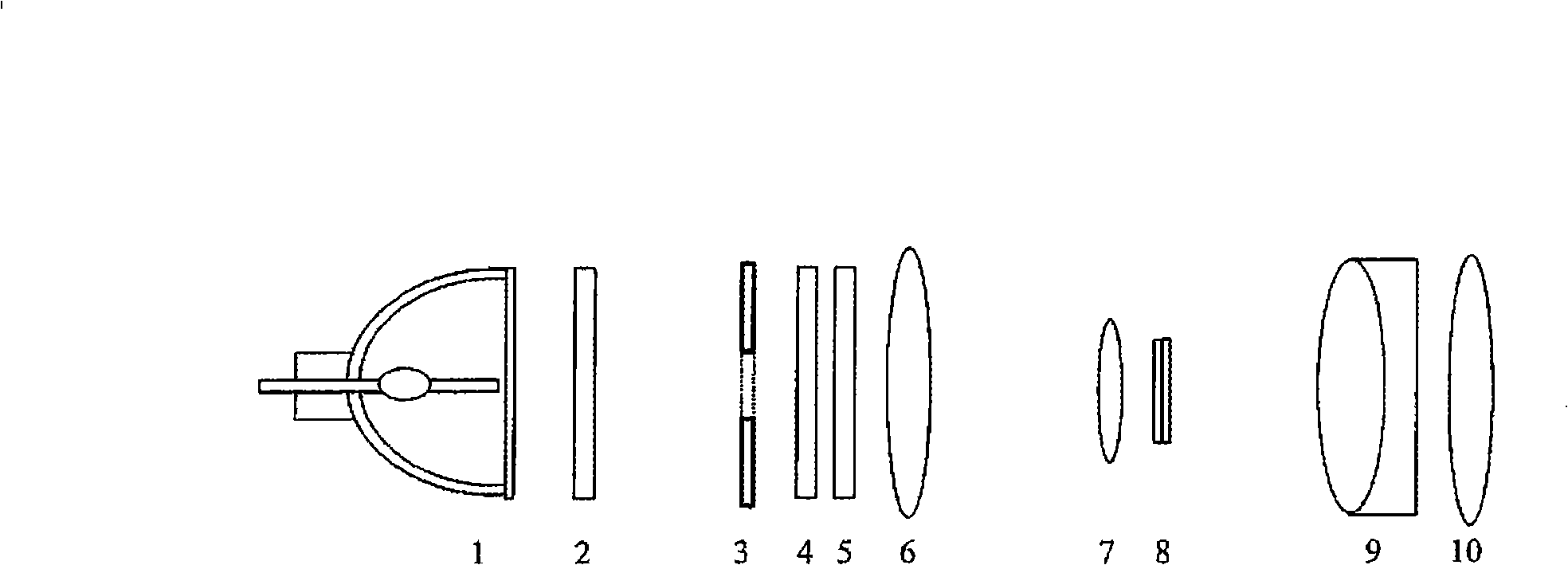
[0038] figure 1 A typical system in the prior art using adjustable mechanical aperture devices is shown. The light emitted by the light source 1 passes through the lens array 2, and the lens array 2 is in optical contact with the mechanical adjustable aperture 3. After the aperture 3, the light passes through the polarization recovery element 5 and then is projected onto an LCD (Liquid Crystal Display) device, which provides modulation of the image, and then projects the image onto a screen (not shown) via projection optics 9.

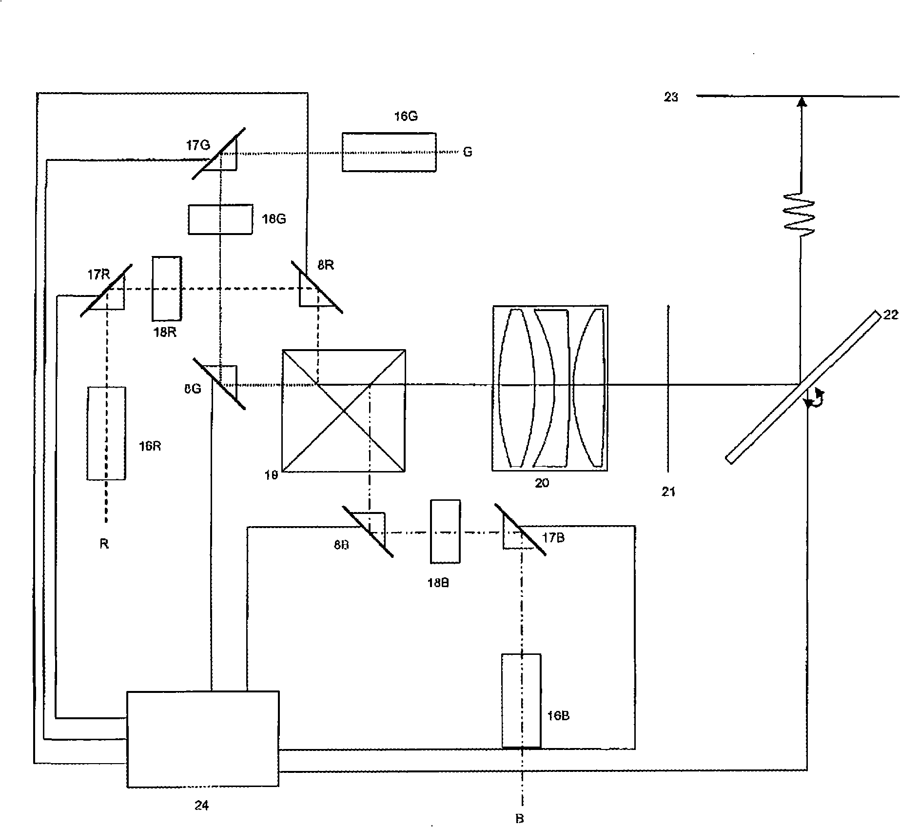
[0039] image 3 An example of an embodiment of a display system for pixel group control according to the present invention is shown, wherein the display system includes a laser light source that is divided into three light sources of red, green, and blue lasers, as those skilled in the art have Known. Three sets of image line generating devices 16R, 16G, and 16B are used to generate three image lines displayed in three different colors. Each image line ...


PUM


Abstract

The present invention is related to a method and system providing dynamic contrast control in scanning line color display systems, and particularly to a method and system comprising at least two modulator units, one for modulating pixel information in a line to be displayed while the other one provides illumination intensity control over different pixel areas or clusters of pixels of said same line to be displayed, by using a tunable diffractive grating element (TDG) in the illumination path to provide image source dependent active brightness level control, i.e. 'dynamic contrast', as well as a shutter function for pixels off transition periods.

Description

Technical field [0001] The present invention relates to a method and system for providing dynamic contrast in a scanning line color display system, and more particularly to a method and system including at least two modulator units, one of which is used to modulate a desired The pixel information in one row is displayed, and the other one provides illumination intensity control for different pixel regions or pixel clusters of the same image line to be displayed. Background technique [0002] The color display system must provide high contrast and grayscale resolution. Below a certain gray level, low contrast will cause image details to be indistinguishable from each other. Low grayscale resolution can also cause image details, artifacts such as contours to be lost. In addition, low grayscale resolution limits the accuracy of color reproduction, especially at low brightness levels. [0003] The minimum black level brightness and thus the maximum contrast of a single pixel in an im...

Claims


Application Information

Patent Timeline
Patent Type & Authority Applications(China)
IPC IPC(8): H04N9/31G02B26/08G02B26/02G02B5/18G02BH04N5/57
CPCH04N5/57G02B26/0808H04N9/3129H04N21/44008H04N9/3179H04N21/4318H04N9/3126
Inventor G·赫丁R·伯格林德T·斯沃特达尔B·斯瓦达尔
Owner POLIGHT
Why Eureka
Try Eureka