Shielding structure of shielding electric wire

A technology of shielding structure and wires, which is applied in the installation of cables, cable connectors, electrical components, etc., can solve the problems of reducing the self-holding force of wires, achieve the effect of enhancing adsorption force and increasing contact area

Active Publication Date: 2007-07-04
YAZAKI CORP
View PDF5 Cites 0 Cited by
  • Summary
  • Abstract
  • Description
  • Claims
  • Application Information

AI Technical Summary

Problems solved by technology

As a result, the wire self-sustaining force is reduced

Method used


Image

  • Shielding structure of shielding electric wire
  • Shielding structure of shielding electric wire
  • Shielding structure of shielding electric wire

Examples


Embodiment Construction

[0068] Embodiments of the present invention will be described in detail below with reference to the accompanying drawings.

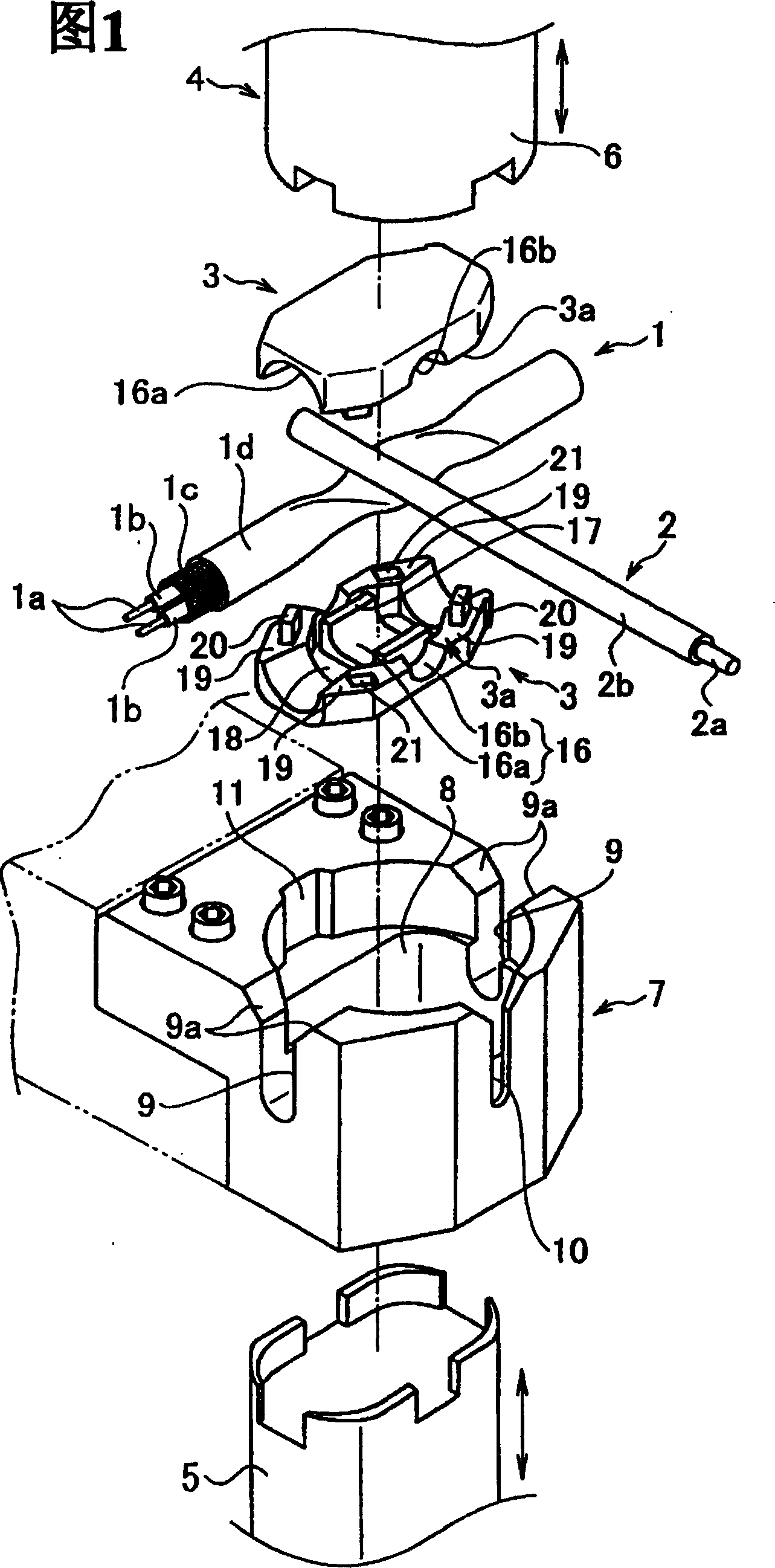
[0069] As shown in FIG. 1, the shielded electric wire 1 is constituted by two core wires 1a and 1a twisted, insulating inner sheaths 1b and 1b respectively covering the peripheral portions of the core wires 1a and 1a by resin, As shielding members, a braided wire 1c for covering the outer peripheral portions of the insulating inner sheaths 1b and 1b, and an insulating outer sheath 1d formed of a resin material covering the outer peripheral portion of the braided wire 1c.

[0070] The ground wire 2 is constituted by the core wire 2a and an insulating outer sheath 2b formed of a resin material and covering the periphery of the core wire 2a.

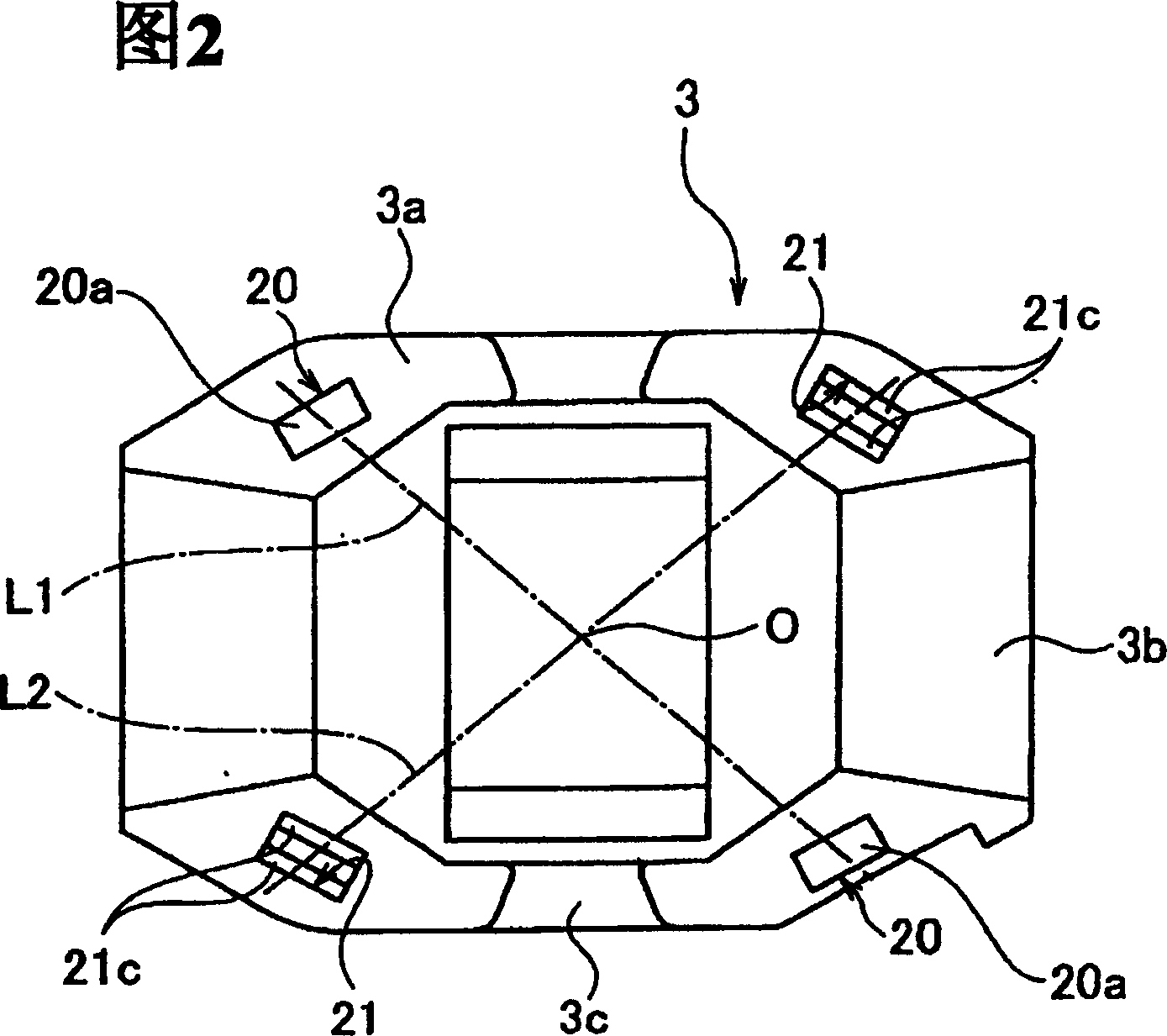
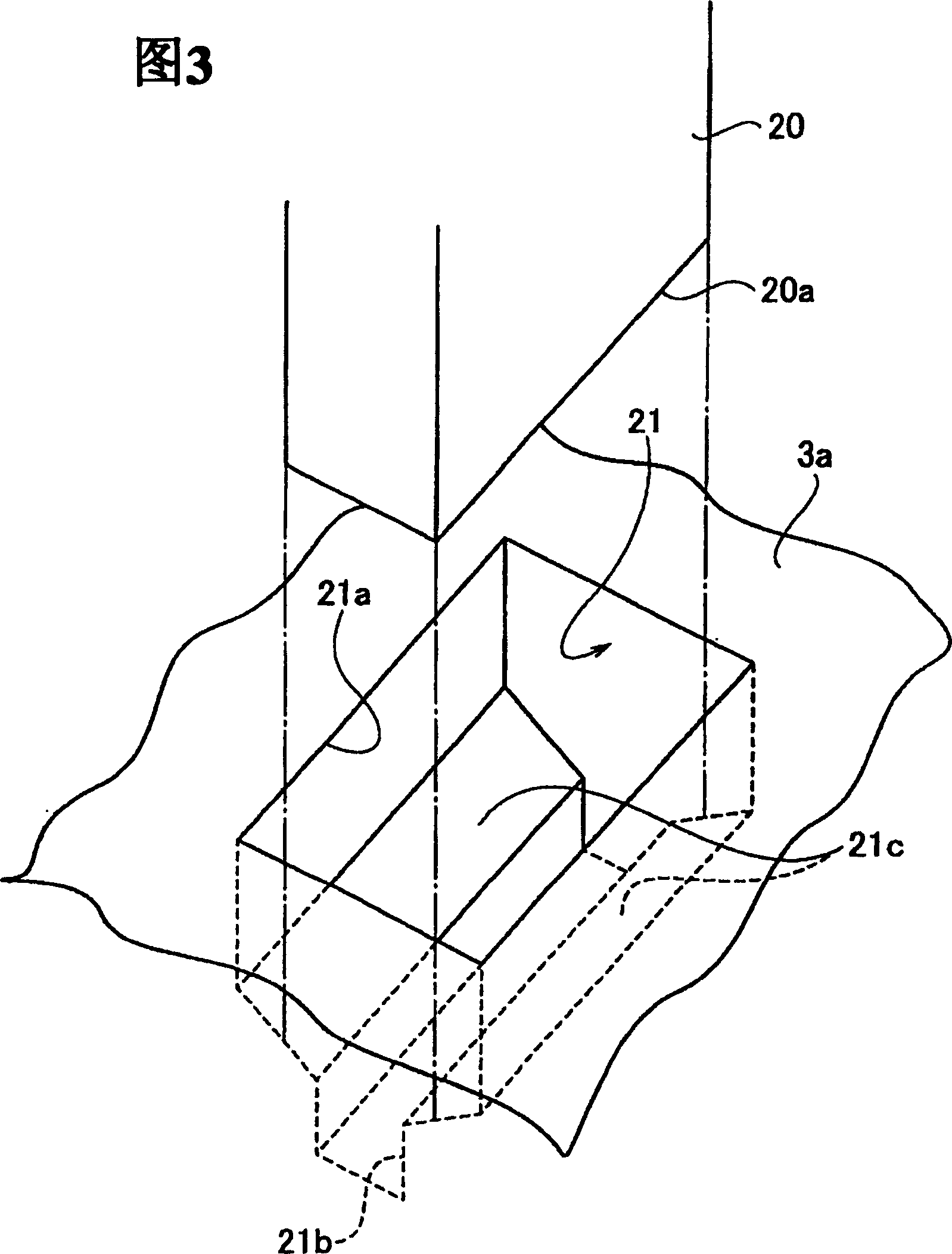
[0071] As shown in FIGS. 1-7, a pair of resin parts 3 and 3 are the same member, and joint faces 3a and 3a are provided with wire abutment faces 16 on which shielded wires 1 and ground wires 2 are respectively abutted. ...


PUM


Abstract

In a shielding structure of a shielding electric wire in which the shielding electric wire and a ground wire are interposed between two resin members, and a compressive force is caused to act on the resin members and an ultrasonic wave is simultaneously applied to fuse the resin portions, thereby forming a shielded portion, a protruded portion 20 is provided on one of junction faces of the two resin members and a hole 21 including a protrusion inserting portion 21a for inserting the protruded portion 20 and a resin inflow portion 21b provided in an inner position from the protrusion inserting portion 21a and having a smaller width than a width of the protrusion inserting portion 21a is provided on the other junction face, and step faces at both sides on a boundary between the protrusion inserting portion 21a and the resin inflow portion 21b in the hole 21 are formed to be a pair of inclined faces 21c and 21c.

Description

technical field [0001] The present invention relates to a shield structure of a shielded electric wire formed by ultrasonically welding a shielded electric wire and a ground wire by means of two resin members. Background technique [0002] A conventional shield structure using ultrasonic welding has been disclosed in Unexamined Japanese Laid-Open No. 2001-6767. The shielding structure is formed by using two resin parts 50 and 51 having arcuate passages 50b and 51b and ultrasonic horns (horn) formed on common joint surfaces 50a and 51a, as shown in Fig. 13(a) and 13(b). More specifically, as shown in FIGS. 14-17 , the ground wire 53 is installed at the upper position of the shielded electric wire 52 with the outer periphery of the core wire 52a covered with a braided wire (shield member) 52c and between the two resin members 50 and 51 The portion of the shielded electric wire 52 of the installation ground wire 53 is interposed so as to provide ultrasonic vibration through t...

Claims


Application Information

Patent Timeline
Patent Type & Authority Patents(China)
IPC IPC(8): H01R4/70H01R4/02H02G15/08H02G15/10H02G15/113
CPCH02G15/113H02G15/10H02G15/085
Inventor 三田晃井出哲郎
Owner YAZAKI CORP
Why Eureka
Try Eureka