Device for setting up central vacuum cleaning installations

A technology for dust removal devices and vacuum cleaners, which is applied in cleaning equipment, applications, vacuum cleaners, etc., can solve problems such as economical impracticality, expensive adsorption devices, and damage

A technology for dust removal devices and vacuum cleaners, which is applied in cleaning equipment, applications, vacuum cleaners, etc., can solve problems such as economical impracticality, expensive adsorption devices, and damage

CN1328999CInactive Publication Date: 2007-08-01奥克·荣松

Image

  • Device for setting up central vacuum cleaning installations
  • Device for setting up central vacuum cleaning installations
  • Device for setting up central vacuum cleaning installations

Examples


Embodiment Construction

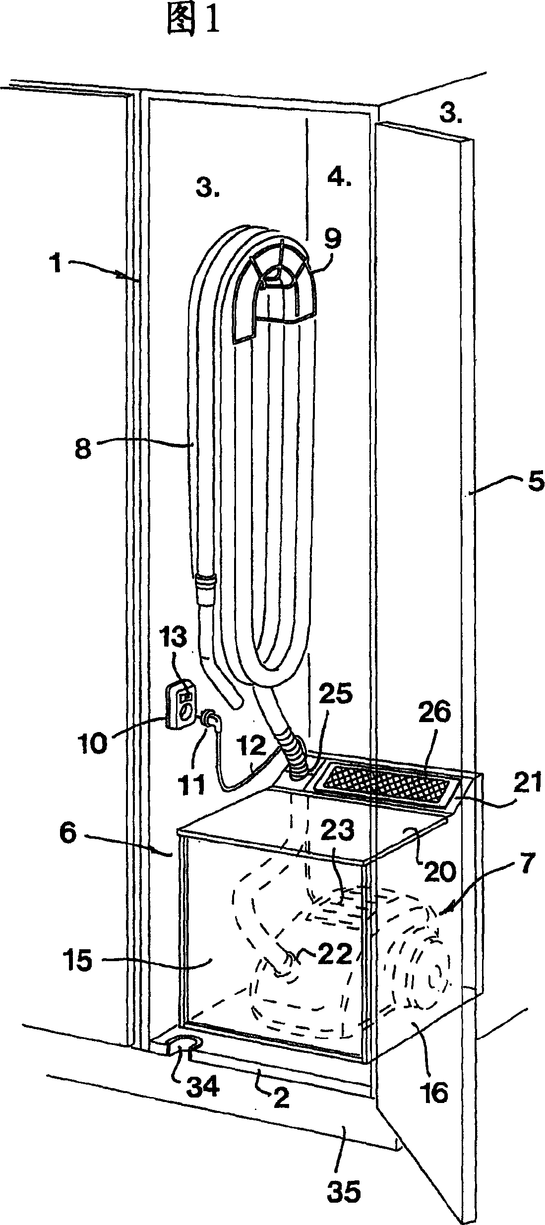
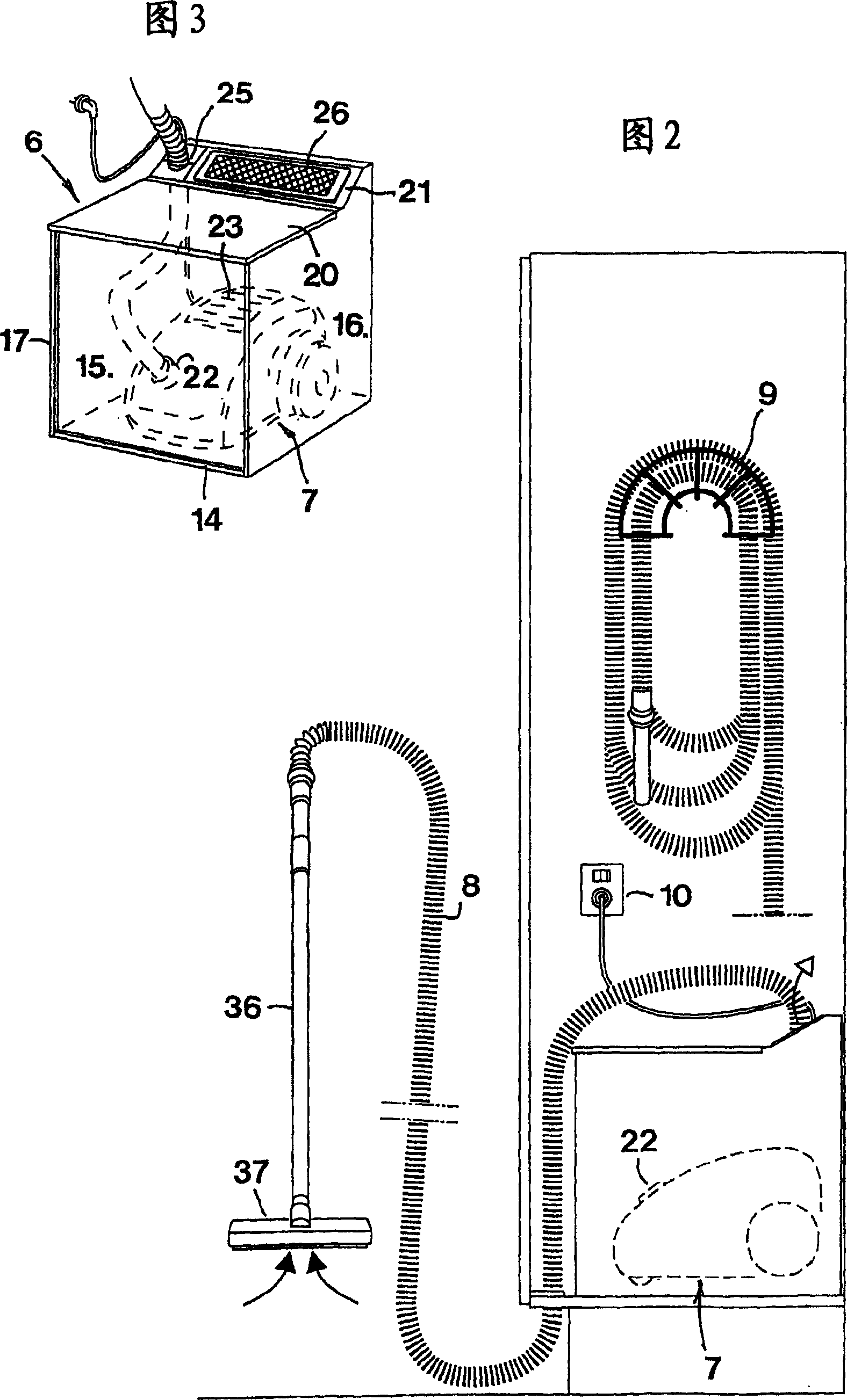
[0018] In Fig. 1, reference numeral 1 generally refers to an existing cabinet, such as a cleaning cabinet, wall cabinet or the like. In addition to a base 2 , two side walls 3 and a rear wall 4 , the cabinet also includes a front door 5 . In this cabinet, the device of the invention is installed in a housing, the housing generally indicated at 6 . A conventional or any type of vacuum cleaner 7 is located in said box, the outline of which is indicated by a dotted line in the figure. A particularly long hose 8 is connected to the vacuum cleaner 7 and the hose 8 can be suspended from a hose bracket 9 fixedly mounted on one of the side walls 3 of the cabinet 3 . On the same side wall of the cabinet where the hose bracket 9 is located, a female connector 10 can preferably be arranged on the side wall, and the plug-in connector 11 of the electric wire 12 can just be inserted into the female connector 10 . Said female connector 10 may preferably include or cooperate with a disconn...


PUM


Abstract

The invention relates to a device for simple setting up of stationary central vacuum cleaning installations in dwellings or the like. The device is in the form of a housing (6) with the purpose of accommodate a conventional vacuum cleaner (7) of the type that comprises an intake air inlet (22) to which a long suction hose (8) is connectable. Parts of the housing are detachable from the rest of the housing in order to enable adjustment of the vacuum cleaner in the interior of the housing. In the housing, an aperture (25) is formed for leading through the hose (8) to the vacuum cleaner, as well as an outlet.

Description

technical field [0001] The invention relates to a device for installing a central vacuum dust collector. Background technique [0002] For example, in residences, offices, hospitals, shops, industrial premises, and the like, vacuuming has long been achieved, first with conventional, mobile vacuum cleaners, including wheel-loaded and motor-driven vacuum cleaners. The fan enclosure draws particulate-laden air from the nozzle tube and hose through a replaceable bag that captures most of the particulate before the air is delivered to the exhaust outlet adjacent to which there is a A fine filter with the required filtration capacity is usually a so-called high-efficiency particulate air (HEPA) filter. Supplying the necessary power to the electric motor is done by means of flexes having plug-in connectors which can be plugged into wall sockets of the type provided at various places in dwellings or other premises. Among them, such a vacuum cleaner is characterized in that the suc...

Claims


Application Information

Patent Timeline
01 Aug 2007
Publication
CN1328999C
IPC
A47L5/38; A47L9/00; A47L7/00
CPC
A47L9/0063; A47L5/38
Inventors
奥克·荣松