Transformer of zero-clearance magnetic circuit and less-clearance magnetic circuit

A transformer and zero-gap technology, applied in the field of new structure transformers, can solve the problems of inability to use grain-oriented electrical silicon steel sheets, reduce transformer efficiency, and low material utilization, and achieve the effects of reducing material costs, improving efficiency and low cost.

Inactive Publication Date: 2014-12-03
SHANGHAI WIND NEW ENERGY TECH
View PDF1 Cites 2 Cited by
  • Summary
  • Abstract
  • Description
  • Claims
  • Application Information

AI Technical Summary

Problems solved by technology

In the field of transformer manufacturing, the cutting and stacking of magnet materials, winding into the core until the closure of the magnetic circuit, the operation process is complicated, and the gap of the magnetic circuit is difficult to completely eliminate, and the reluctance generated at the joint gap is larger than that of other parts of the magnetic circuit Large gaps will increase the excitation current and reduce the efficiency of the transformer. At the same time, due to the noise of the transformer in the gap of the magnetic circuit seam, it will disturb people and affect the environment. Therefore, how to reduce and shorten the seam during the construction of the transformer The gap is one of the important contents of the quality control of the transformer, and it is also a special emphasis of the process specification
Aiming at the magnetic circuit gap of traditional transformers, the structure of the zero-gap magnetic circuit concept proposed in the patent application 201310160702.1 "Zero-Gap Magnetic Circuit Self-enclosed Transformer" has an obvious effect on reducing the magnetic circuit gap, but for the production of specific products, how to compare with the existing There are practical problems such as the lack of grain-oriented electrical silicon steel sheets and the low utilization rate of materials in the use of a full zero-gap magnetic circuit. A combination of zero-gap magnetic circuit technology and traditional transformer overall material technology is needed. Implementation of intermediate structure solutions

Method used


Image

  • Transformer of zero-clearance magnetic circuit and less-clearance magnetic circuit
  • Transformer of zero-clearance magnetic circuit and less-clearance magnetic circuit
  • Transformer of zero-clearance magnetic circuit and less-clearance magnetic circuit

Examples


Embodiment Construction

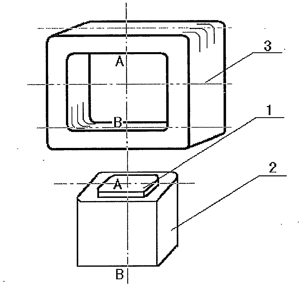
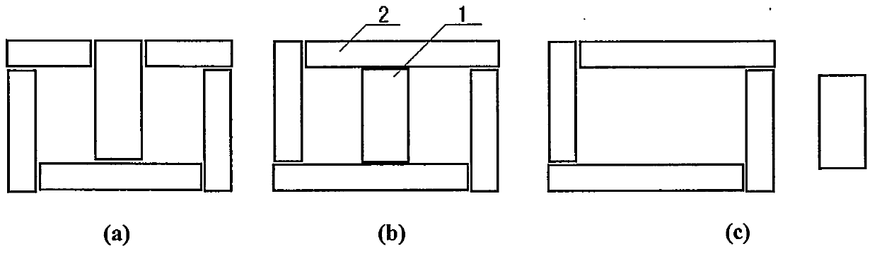
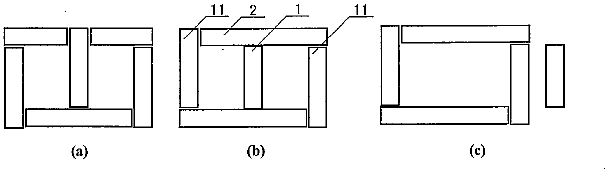
[0013] The main structure of the transformer structure of the present invention includes two parts - a winding and a magnetic circuit, and the magnetic circuit can be decomposed into an iron core and an iron yoke. The iron core (1) is a component for installing the winding, and is also the source of the magnetic force flow generated by the current in the winding. The winding (2) is an important part of electromagnetic coupling - the electric chain. The input current of the winding can generate magnetic force lines in the iron core, and can also generate induced voltage through the change of the magnetic force lines to output power, thereby outputting AC current outward. The iron yoke (3) is a passage for connecting the magnetic current (single phase) in the iron core or the magnetic current (three phase) between the iron cores, for the circulation of the magnetic field lines in the iron core, and completing the flux linkage. The iron core and the iron yoke form a magnetic circu...


PUM


Abstract

The invention discloses a novel structure of a transformer of a zero-clearance magnetic circuit and a less-clearance magnetic circuit. By adopting the technology of combining the advanced process of the zero-clearance magnetic circuit with a traditional structure of an existing large-scale transformer, the seam magnetic resistance can be effectively reduced, the magnetizing current and the noise of the transformer can be reduced, the efficiency of the transformer is increased, and the transformer is mute and does not disturb people; procedures of stacking and sealing off are simplified; the materials and the installation cost are reduced, and the transformer of the zero-clearance magnetic circuit and the less-clearance magnetic circuit is a great innovation in manufacturing technology practice after the structure of a zero-clearance magnetic circuit transformer is invented.

Description

technical field [0001] The invention belongs to the transformer in the field of electrical technology, and relates to the improvement of the magnetic circuit structure of the transformer, in particular to a transformer with a new structure capable of reducing the reluctance magnetic loss of the magnetic circuit seam. Background technique [0002] The basic principle of a transformer is the interlinkage of the winding (circuit) and the magnetic circuit. To put the winding into the magnetic circuit, the magnetic circuit must be fabricated in sections to allow the winding to be embedded, and a seam gap must be left on the magnetic circuit. In the field of transformer manufacturing, the cutting and stacking of magnet materials, winding into the core until the closure of the magnetic circuit, the operation process is complicated, and the gap of the magnetic circuit is difficult to completely eliminate, and the reluctance generated at the joint gap is larger than that of other part...

Claims


Application Information

Patent Timeline
Patent Type & Authority Applications(China)
IPC IPC(8): H01F27/24H01F30/12
Inventor 於岳亮於宙
Owner SHANGHAI WIND NEW ENERGY TECH
Why Eureka
Try Eureka