Template unit for cast-in-place concrete wall and construction method thereof

A concrete wall and formwork technology, which is applied in the field preparation of formwork/formwork/work frame, building components, construction, etc., can solve the problems of affecting the quality of concrete molding and project cost, unstable construction quality, and low turnover times of formwork To achieve the effect of shortening the construction period, improving the quality of joints, and reducing energy consumption

Active Publication Date: 2012-01-18
CHANGZHOU NO 1 CONSTR GRP
View PDF0 Cites 0 Cited by
  • Summary
  • Abstract
  • Description
  • Claims
  • Application Information

AI Technical Summary

Problems solved by technology

[0002] Most of the existing high-rise residential buildings are reinforced concrete shear wall structures, and most of them are constructed with loose-branched and dismantled plywood formwork systems. The construction quality is unstable, and the formwork turnover times are low, which affects the quality of concrete molding and project costs.

Method used


Image

  • Template unit for cast-in-place concrete wall and construction method thereof
  • Template unit for cast-in-place concrete wall and construction method thereof
  • Template unit for cast-in-place concrete wall and construction method thereof

Examples


Embodiment Construction

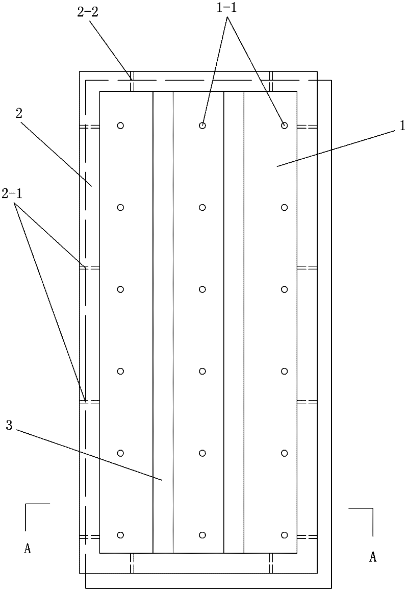
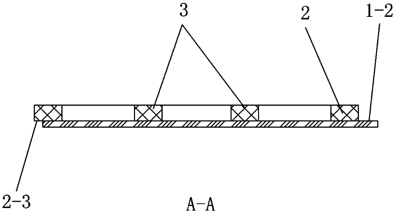
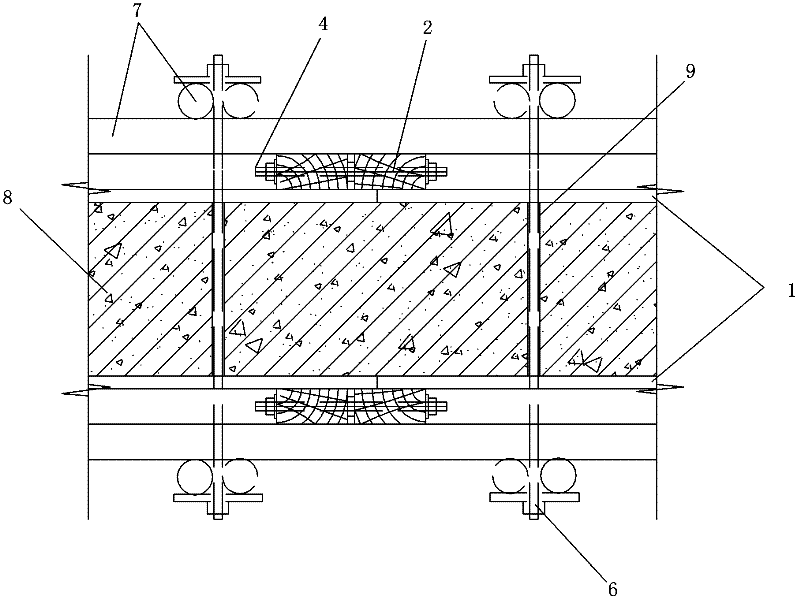
[0022] See Figure 1-4 , the formwork unit for the cast-in-place concrete wall of the present embodiment includes: a rectangular plywood 1 and splicing wooden frames 2 arranged on four sides of the plywood 1; Horizontal splicing bolt holes 2-1 are provided on the vertical frame of the frame 2, and vertical splicing bolt holes 2-2 are provided on the horizontal frame of the splicing wooden frame 2; the lower edge and the right edge 1-2 of the plywood 1 extend out of the splicing wooden frame 2. The upper and left edges 2-3 of the spliced ​​wooden frame 2 extend out of the plywood 1 .

[0023] The plywood 1 is also provided with a corrugated wood 3 fixed in the spliced ​​wooden frame 2 . The six end faces of the plywood 1 are sealed with film. It is also possible to seal all the processing places of the plywood 1 with novolac varnish. The width of the lower edge and the right edge 1-2 of the plywood 1 extending out of the splicing wooden frame 2 is 5-15mm larger than the widt...


PUM


Abstract

The invention relates to a template unit for cast-in-place concrete wall which is simple in structure and is suitable for improving circulation times of the template and ensuring molding quality of the concrete and a construction method thereof. The template unit comprises a plywood and a jointed wood frame which is arranged on the plywood, wherein a plurality of counter-pull bolt holes are distributed on the plywood; horizontal jointing bolt holes are formed on vertical side frames of the jointed wood frame; vertical jointing bolt holes are formed on a horizontal side frame of the jointed wood frame; a lower edge and a right edge of the plywood extend 40mm out of the jointed wood frame; and an upper edge and a left edge of the plywood extend 30mm out of the jointed wood frame. During construction, the jointed wood frame between adjacent template units and a corresponding edge of the plywood are laminated, and the jointed wood frame and the plywood between the adjacent template units have a gap of 10mm in between and are fastened by a jointing bolt. Therefore, the flatness of a wall surface at a jointed part and the tightness of a joint seam are ensured and the requirement on as-cast finish concrete is met.

Description

technical field [0001] The invention relates to a formwork unit for cast-in-situ concrete walls and a construction method thereof. Background technique [0002] Most of the existing high-rise residential buildings are reinforced concrete shear wall structures, and most of them are constructed with loose-branched and dismantled plywood formwork systems. The construction quality is unstable, and the formwork turnover times are low, which affects the quality of concrete molding and project costs. Therefore, how to increase the turnover times of the shear wall formwork, simplify the construction process and ensure the quality is a technical problem to be solved in this field. Contents of the invention [0003] The technical problem to be solved by the present invention is to provide a formwork unit for cast-in-place concrete walls and a construction method thereof, which has a simple structure, is suitable for increasing the turnover times of the formwork, and can ensure the q...

Claims


Application Information

Patent Timeline
Patent Type & Authority Patents(China)
IPC IPC(8): E04G11/06E04G11/08
Inventor 庄彤
Owner CHANGZHOU NO 1 CONSTR GRP
Why Eureka
Try Eureka