Energy saving reactor with unlaminated core

A non-lamination type, reactor technology, applied in the direction of transformer/inductor magnetic core, circuit, electrical components, etc., can solve the problems of high manufacturing cost, reduce inductance, increase copper loss, etc., to reduce manufacturing difficulty and man-hours cost, reduce the magnetic circuit seam gap, and reduce the effect of copper loss

Inactive Publication Date: 2016-08-24
SHANGHAI WIND NEW ENERGY TECH
View PDF1 Cites 0 Cited by
  • Summary
  • Abstract
  • Description
  • Claims
  • Application Information

AI Technical Summary

Problems solved by technology

In order to reduce the loss of magnetic energy, in the power frequency range, the iron core is usually made of thin silicon steel sheets. To put the winding into the magnetic circuit, except for the case of flowing direct current or deliberately increasing the leakage reactance to prevent the saturation of the magnetic circuit, for pure In terms of alternating current, it is hoped that the air gap of the magnetic circuit should be as small as possible, because although the air gap is small, but because the magnetic permeability of air is much lower than that of ferromagnetic materials, the air gap will increase the reluctance and reduce the inductance. In order to make up for the inductance , it is bound to increase the number of winding turns, which will increase the copper loss; in addition, in many traditional iron core reactors, for the sake of manufacturing convenience, the iron core cross section is rectangular, and the circumference of the rectangular winding is larger than the circular cross section under the same cross section area, so the copper loss Higher than the circular winding, it will also increase the copper loss; and in order to reduce the copper loss, the laminations with different widths are stacked into a circle, the process is very complicated, and the stacking requirements are very strict, which is not as convenient as the lamination of the rectangular cross-section of the iron yoke Economical, making man-hours very inefficient for manufacturing core reactors
[0005] In short, the existing core reactor has large loss, complex process structure, high manufacturing cost, and requires major structural improvement

Method used


Image

  • Energy saving reactor with unlaminated core
  • Energy saving reactor with unlaminated core
  • Energy saving reactor with unlaminated core

Examples


Embodiment Construction

[0026] Reactor is an important electrical device, which is widely used in power system to limit power frequency overvoltage, eliminate generator self-excitation, limit operating overvoltage, line capacitive charging power, suppress potential supply current, limit short-circuit current, etc. Function. As a means of reactive power compensation, reactors are also indispensable in power systems. The reactor is also a filter device, which can filter out high-order harmonics, adjust power factor, and reduce grid voltage distortion.

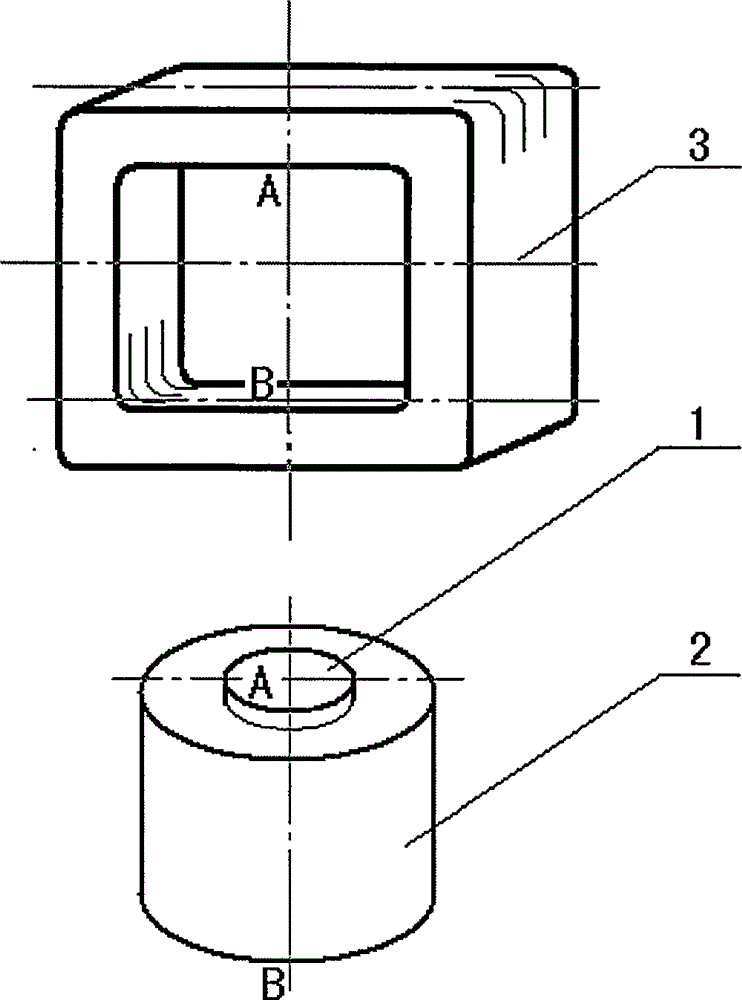
[0027] The reactor of the invention is a high-efficiency energy-saving reactor with an iron core. Increasing the core of the reactor can increase the inductance of the reactor, reduce the volume and weight, and effectively reduce the copper loss.

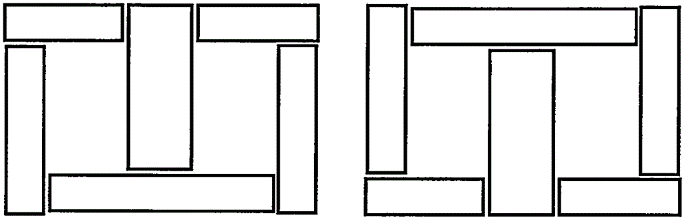
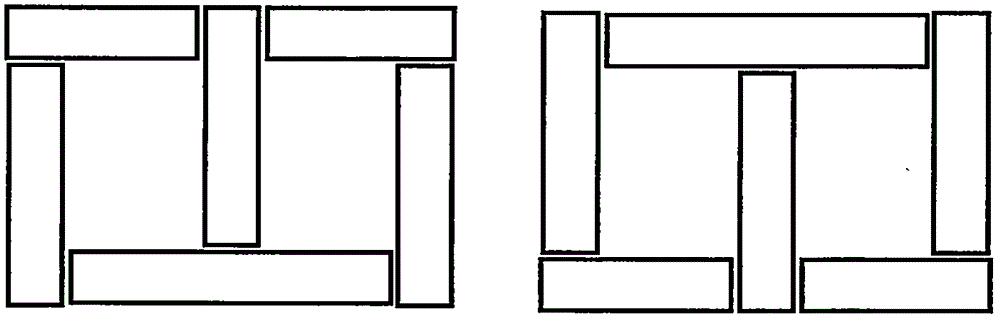
[0028] The definition of the magnetic circuit structure of the reactor of the present invention is different from that of the traditional reactor, and must be defined separately.

[0029] In the present in...


PUM

PropertyMeasurementUnit
thicknessaaaaaaaaaa
thicknessaaaaaaaaaa
thicknessaaaaaaaaaa

Abstract

The invention provides an energy saving reactor with an unlaminated core. The energy saving reactor is a multi-technology with improved structure and process in the field of medium and large transformer manufacturing. A zero-clearance magnetic circuit is arranged to obtain the lowest iron loss and lowest man-hour and manufacturing cost. By the technology of replacing a laminated core with a wound core, a round cross-section core and a rectangular cross-section yoke can obtain the optimal process fitting; the core laminating cost is reduced; the magnetic loss is reduced; the energy saving reactor is suitable for manufacturing of a core-type or shell-type reactor of which the power is from tens of kilowatts to hundreds of thousands of kilowatts, and is a significant innovation in the structure and the process technology in the field of the reactor.

Description

field of invention [0001] The invention belongs to the technical field of inductive reactors in electricity, and relates to a magnetic circuit structure and a manufacturing method of an iron-core reactor, specifically, an energy-saving reactor with a new structure and a new process. Background technique [0002] A reactor is an important electrical device, and in a narrow sense it usually refers to a device that can provide inductive reactance. Widely used in power systems, power electronic systems, and electronic circuits, it is an indispensable electrical device and electronic component. [0003] As an electromagnetic induction device, in order to obtain greater inductance and make it more compact, or to limit the magnetic flux of the winding to a certain space, it is often necessary to set an iron core in the winding, which becomes an iron core reactor. [0004] The basic structure of the iron core reactor is the cross-linking of the circuit (including winding and extern...

Claims


Application Information

Patent Timeline
Patent Type & Authority Applications(China)
IPC IPC(8): H01F27/24H01F41/02H01F17/04
Inventor 於岳亮雷雪
Owner SHANGHAI WIND NEW ENERGY TECH
Why Eureka
Try Eureka