Rotational flow mercury adsorbent injection device

A technology of spraying device and adsorbent, which is applied in the directions of spraying device, spraying device, liquid spraying device, etc., can solve the problems of inability to effectively control the air intake and feed amount, increase the construction cost and maintenance cost, and narrow the flow trajectory of the adsorbent. , to improve the mercury adsorption efficiency, reduce the cost of mercury removal, and improve the efficiency of mercury removal

Active Publication Date: 2017-12-19
HUAZHONG UNIV OF SCI & TECH
View PDF12 Cites 2 Cited by
  • Summary
  • Abstract
  • Description
  • Claims
  • Application Information

AI Technical Summary

Problems solved by technology

In laboratory fixed bed mercury removal experiments, most of the mercury removal adsorption materials have high adsorption efficiency, but in the actual flue, comparing the mercury concentration in the flue gas before and after spraying, it is found that the mercury concentration in the flue gas has not decreased significantly
For the existing sorbent injection device, one sorbent injection device has only one nozzle. Through the CFD injection simulation, it is found that the flow trajectory of the sorbent in the flue is very narrow, and it cannot diffuse to the entire flue section and fully mix with the flue gas. During the production process, large-scale arrangement of injection devices will increase construction costs and maintenance costs
In addition, some adsorbent injection devices cannot effectively control the air intake and feed volume, resulting in a large amount of waste of adsorbent and increasing the cost of mercury removal

Method used


Image

  • Rotational flow mercury adsorbent injection device
  • Rotational flow mercury adsorbent injection device
  • Rotational flow mercury adsorbent injection device

Examples


Embodiment Construction

[0029] In order to make the object, technical solution and advantages of the present invention clearer, the present invention will be further described in detail below in conjunction with the accompanying drawings and embodiments. It should be understood that the specific embodiments described here are only used to explain the present invention, not to limit the present invention. In addition, the technical features involved in the various embodiments of the present invention described below can be combined with each other as long as they do not constitute a conflict with each other.

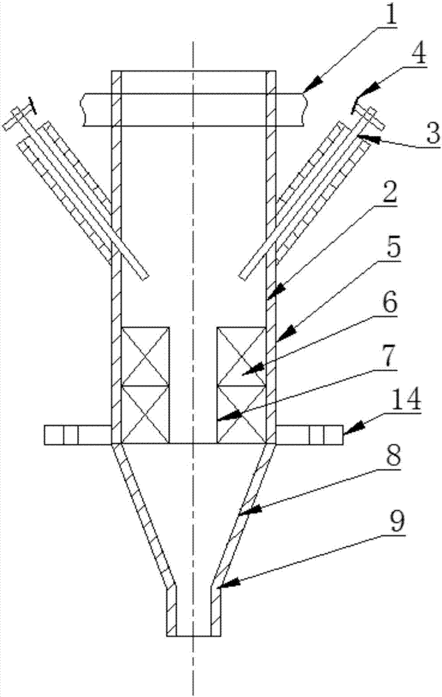
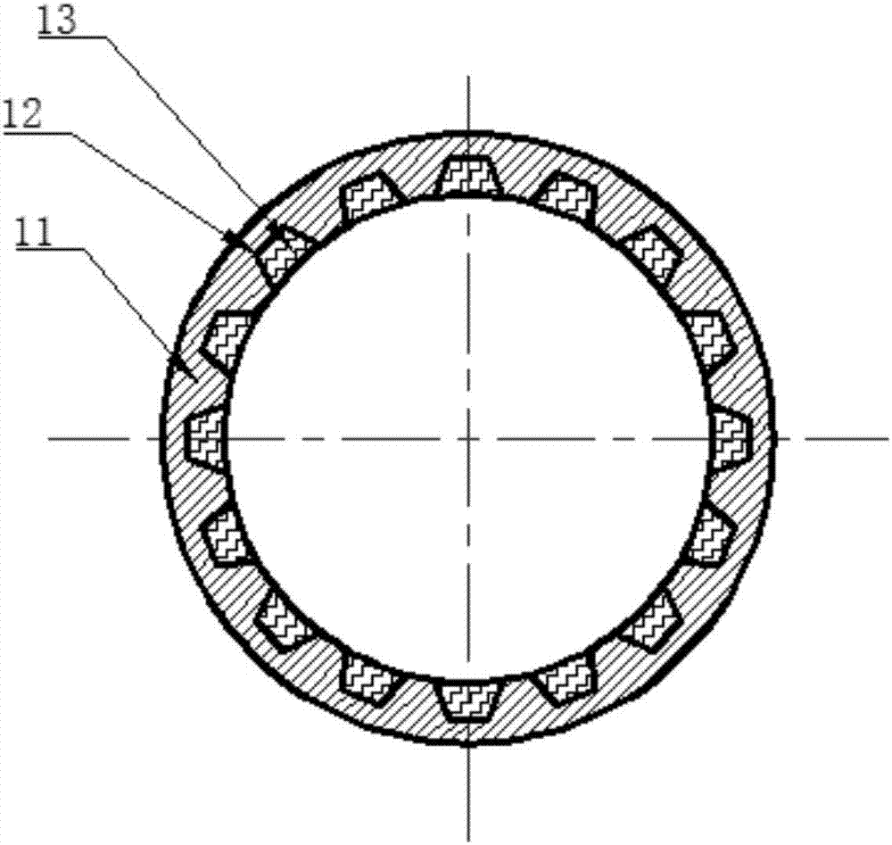
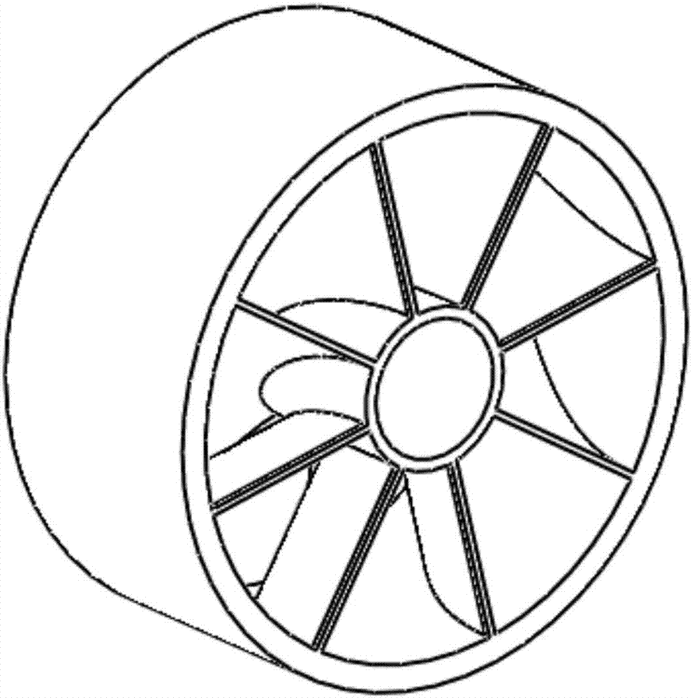
[0030] see figure 1 , figure 2 , image 3 and Figure 4 , the swirl mercury sorbent injection device provided by the preferred embodiment of the present invention, the swirl mercury sorbent injection device includes a damper 1, a main spray barrel 2, two spray guns 3, two regulating valves 4, a sound-absorbing Mechanism 5, two swirl impellers 6 and flange 14. The air valve 1 is arranged at...


PUM


Abstract

The invention belongs to the relevant technical field of mercury control in coal-fired flue gas, and discloses a rotational flow mercury adsorbent injection device. The device comprises a main injection barrel and two rotational flow impellers. The main injection barrel comprises a straight line section, a nozzle and a contraction section for connecting the straight line section with the nozzle. The contraction section is in a conical shape, the opening diameter of the end, connected with the straight line section, of the contraction section is larger than the opening diameter of the end, connected with the nozzle, of the contraction section, the two rotational flow impellers are stacked to the straight line section, air entering the straight line section form direct flow air and rotational flow air after passing through the rotational flow impellers, the direct flow air and the rotational flow air are mixed to drive a mercury adsorbent entering the containing cavity to enter the contraction section and accelerated through the contraction section and then enter the nozzle, and the nozzle is used for injecting the mercury adsorbent into a flue to be mixed with smoke gas in the flue for mercury adsorption and removal. The mixed gas is accelerated through the contraction section, the contact probability of the mercury adsorbent and smoke gas is increased, and the mercury adsorption efficiency is improved.

Description

technical field [0001] The invention belongs to the related technical field of mercury control in coal-burning flue gas, and more specifically relates to a swirling mercury adsorbent injection device. Background technique [0002] Mercury is a kind of nerve poison, which is highly cumulative and irreversible, and poses a great threat to human health. Coal-fired power plants are one of the most important sources of anthropogenic mercury pollution. With the continuous improvement of environmental protection requirements, it is of great significance to seek efficient, economical and environmentally friendly mercury control technologies. [0003] In the prior art, mercury removal devices are usually used to remove mercury in flue gas by using high-efficiency adsorption materials. The current main research focuses on two aspects: mercury removal adsorption materials and mercury removal devices. The research on mercury removal adsorption materials mainly focuses on changing raw ...

Claims


Application Information

Patent Timeline
Patent Type & Authority Applications(China)
IPC IPC(8): B05B7/04B05B15/00B05B1/00B01D53/10
CPCB01D53/10B05B1/00B05B7/0425B05B15/00B01D2257/602B01D2258/0283
Inventor 赵永椿朱彬彬孔凡淇张军营郑楚光
Owner HUAZHONG UNIV OF SCI & TECH
Why Eureka
Try Eureka