Electrolytic water and its generating device

A generation device and electrolyzed water technology, applied in water/sewage treatment, water/sewage treatment equipment, water/sludge/sewage treatment, etc., can solve problems such as high price, harmful gas treatment, and regular replacement, and achieve structural Inexpensive, long-term stable use, simple structure and effective

Inactive Publication Date: 2002-01-23
PANASONIC CORP
View PDF3 Cites 29 Cited by
  • Summary
  • Abstract
  • Description
  • Claims
  • Application Information

AI Technical Summary

Problems solved by technology

[0004] However, when it is used to wash common dirt, such as oil stains attached to the kitchen wall, or oil fumes attached to glass or furniture, etc., the sodium ions or potassium There are few ions and the overall pH is low, so the conditions for sufficient washing power are not yet available
According to the experimental results of the washing performance of the greasy stains attached to the ceramic tiles carried out by the present inventor, there is no sufficient washing power at pH below 11.5. In addition, when the sodium ion concentration is

Method used


Image

  • Electrolytic water and its generating device
  • Electrolytic water and its generating device
  • Electrolytic water and its generating device

Examples


Embodiment 1

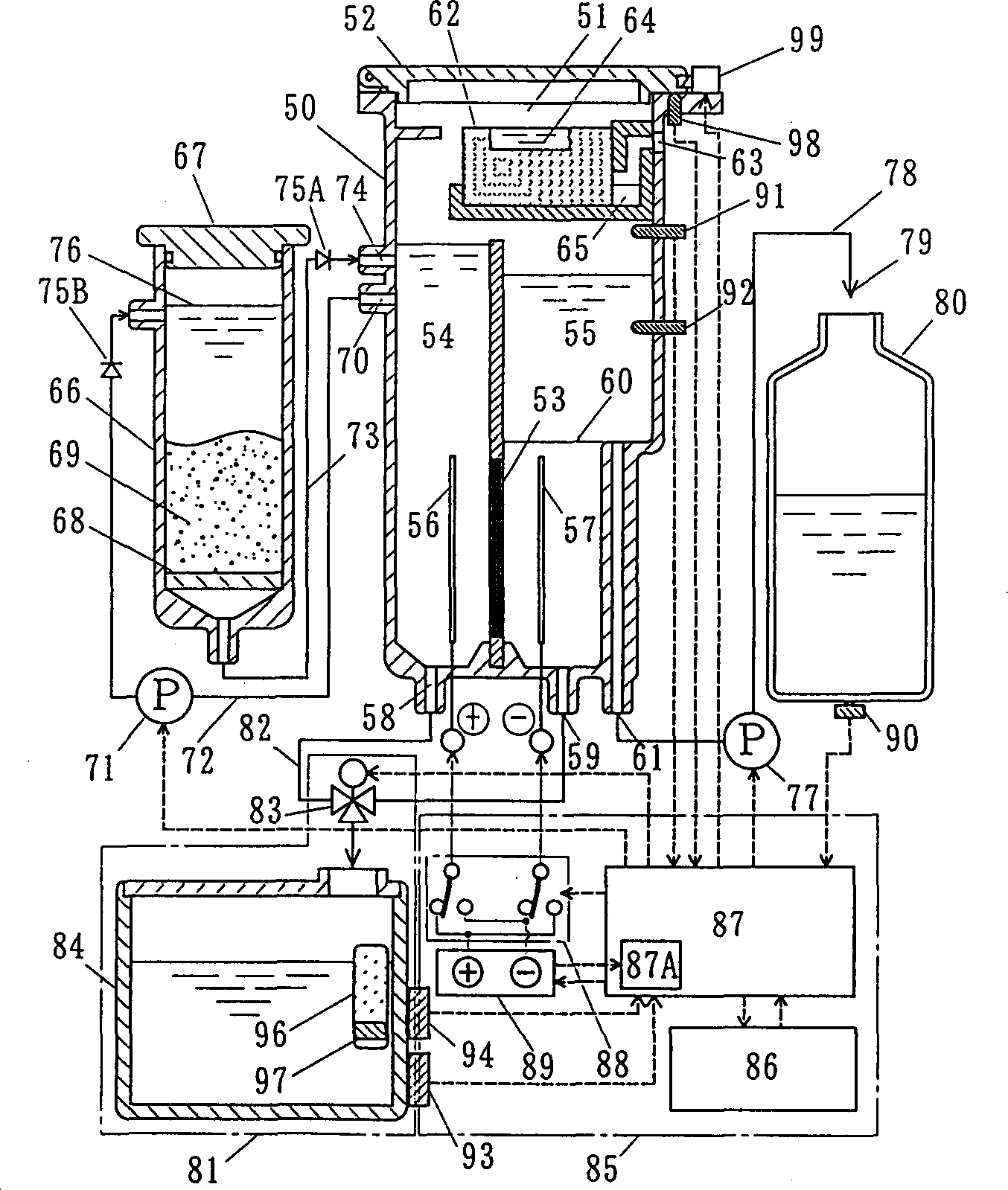
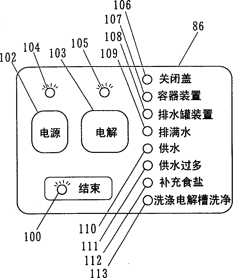
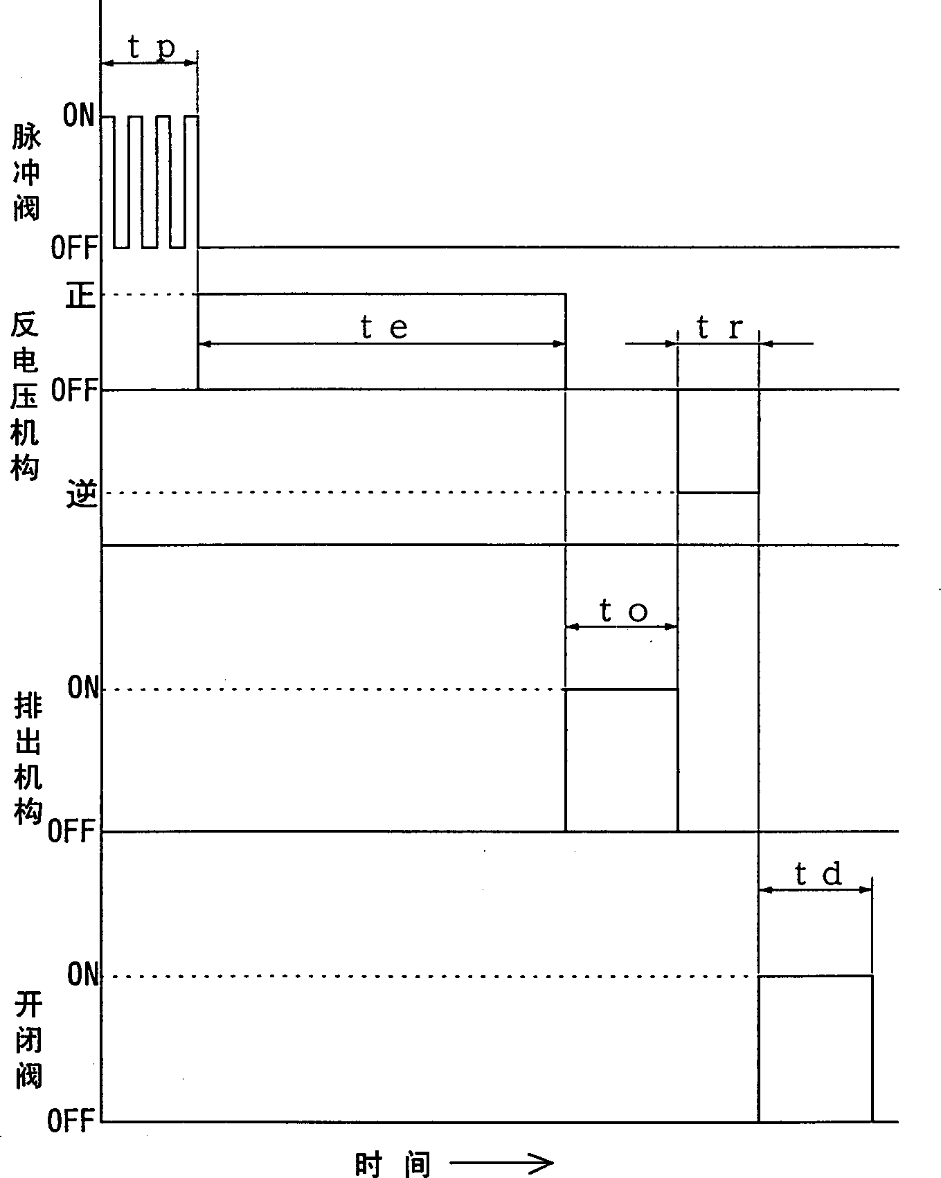
[0120] figure 1 A configuration diagram showing an electrolyzed water generator according to Example 1 of the present invention. figure 2 It shows the operation panel of the control mechanism of Embodiment 1 of this invention. image 3 A time chart showing the control operation of Embodiment 1 of the present invention. Figure 4 An external view showing the electrolyzed water generating device of Example 1 of the present invention. Figure 5 A state characteristic diagram showing hydrogen ion concentration (pH) and available chlorine.

[0121] This example shows the case where alkaline water is used as electrolyzed water and used as washing water. figure 1 Describe the center. exist figure 1 Among them, 50 is an electrolytic cell that closes the water supply port 51 at the upper end with an electrolytic cell cover 52 to make it into a sealed state, and an anode chamber 54 and a cathode chamber 55 are formed by an ion-permeable diaphragm 53, and each anode 56 and catho...

Embodiment 2

[0198] Figure 11 A configuration diagram showing an electrolyzed water generator according to Example 2 of the present invention. In addition, the same code|symbol is used for the same structure as the electrolyzed water generator of Example 1, and description is abbreviate|omitted.

[0199] exist Figure 11 In the process, the electrolyte retaining part 130 for retaining the salt water at the bottom of the anode chamber 54 of the electrolytic cell 50 and the interface 131 between the high-concentration salt water and the raw material are formed.

[0200] The electrolyte is saturated brine supplied from the electrolyte tank 66. When a predetermined amount of saturated brine is supplied to the raw water in the anode chamber 54, the brine sinks to the bottom of the anode chamber 54 due to its specific gravity difference. Then, it stays in the electrolyte storage part 130 . At this time, the saturated salt water is slightly diluted, but still maintains a high concentration of...

Embodiment 3

[0205] Figure 12 A configuration diagram showing an electrolytic cell of an electrolyzed water generator according to Example 3 of the present invention. In addition, the same structure as the electrolyzed water generator of Example 1 and Example 2 is assigned the same code|symbol, and the description is abbreviate|omitted.

[0206] exist Figure 12 In the anode chamber 54 of the electrolytic cell 50, an inclined surface A136 and an inclined surface B137 are provided at the bottom of the anode chamber 54, and an electrolyte retention part 138 for retaining electrolyte saline is formed. The electrolyte is saturated saline supplied from the electrolyte tank 66 , which settles to the bottom of the anode chamber 54 due to the difference in specific gravity, is introduced from the inclined surface A136 and the inclined surface B137 , and accumulates in the electrolyte retention part 138 . At this time, although the saturated salt water becomes slightly thinner, it still maintain...


PUM


Abstract

Provided is an electrolytic water production apparatus, the apparatus is equipped with an electrolytic cell, wherein an ion permeable diapheragm is arranged between an anode and a cathode, and a control means 48 for stopping the application of power in such a state that electrolytic water formed in the cathode chamber becomes alkaline water with a pH of 11.5-12.5 when the water is fed in the anode chamber and the cathode chamber and an high concentration electrolyte is put in at least the anode chamber to electrolyze water to be electrolyzed. This electrolyzed water making apparatus can be installed easily in a home or an office and safe electrolyzed water excellent in washing power is obtained.

Description

technical field [0001] The invention relates to a highly alkaline electrolyzed water generated by electrolyzed water and an electrolyzed water generating device thereof. technical background [0002] Among the electrolyzed water generators, there are a flow-type type that is connected to water supply equipment such as tap water and performs electrolysis in a flowing state to produce acidic water or alkaline water, and a simple and low-cost structure that is not connected to a water supply equipment and performs electrolysis in a non-flowing state. Two forms of intermittent water. Although the flow-through device has the advantage of being able to obtain electrolyzed water immediately, however, in the case of both oxidizing strongly acidic water and reducing strongly alkaline water, large electrodes and high power are required, and at the same time Complicated structure, and increase the overall cost of the device. On the other hand, with a batch-type device, although it ma...

Claims


Application Information

Patent Timeline
IPC IPC(8): C02F1/461
CPCC02F1/4618C02F2201/4611C02F2201/46115C02F2209/06C02F2209/42
Inventor 国本启次郎白井滋松本朋秀桶田岳见冈浩二河合祐中村一繁
Owner PANASONIC CORP
Why Eureka
Try Eureka