
Droplet deposition apparatus

A deposition device, droplet technology, applied in inking devices, metal processing equipment, printing, etc., can solve problems such as difficult-to-channel electrode connection

Inactive Publication Date: 2002-01-30
XAAR TECH LTD
View PDF16 Cites 12 Cited by
  • Summary
  • Abstract
  • Description
  • Claims
  • Application Information

AI Technical Summary

Problems solved by technology

But it is still difficult to establish a connection to the channel electrode

Method used


Image

  • Droplet deposition apparatus
  • Droplet deposition apparatus
  • Droplet deposition apparatus

Examples


Embodiment Construction

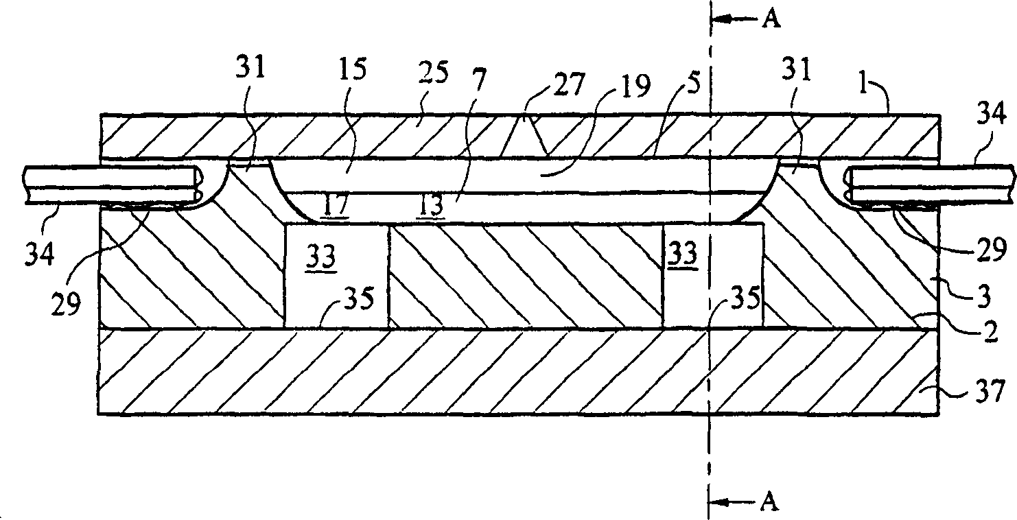
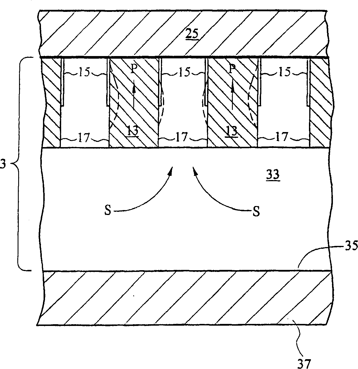
[0025] Figure 1 shows a prior art inkjet printhead 1 of the type disclosed in WO 91 / 17051 comprising a plate 3 of piezoelectric material such as lead zirconium titanate (PZT) whose top surface forms There is an array of ink channels 7 that are open at the top. Fig. 2 is a sectional view along the line AA of Fig. 1, can obviously find out from this figure, the continuous channel in the array is separated by side wall 13, and wherein side wall 13 includes connecting plate 3 thickness direction (as arrow Piezoelectric material shown in P). Arranged on the opposite channel-facing surface 17 is an electrode 15 , to which an electrical voltage can be applied via a connection 34 . It is known, for example, from EP-A-0364136 that an electric field between electrodes on either side of a wall causes the wall to bend in shear mode towards a side channel, which is shown enlarged by the dotted line in Figure 2, so that in this channel A pressure pulse is generated.

[0026] These channe...


PUM


Abstract

A method of manufacturing an ink jet print head includes the steps of bonding a body of piezoelectric material to a base plate and cutting channels into the piezoelectric material to form ink chambers which are actuated by applying voltages to electrodes provided on surfaces of the chambers. The base plate carries IC's which contain the drive circuitry for actuating the ink chambers. To ensure reliable electrical connection between the chamber electrodes and the IC's, the electrodes and conducting tracks on the base plate are formed in a single step by depositing a conductive layer over both the PZT body and the base plate. A step of masking or selective removal of material may be performed to achieve the necessary patterning of the electrodes and tracks.

Description

technical field [0001] The present invention relates to droplet deposition devices, and more particularly to inkjet printheads, components thereof and methods of making the same. Background technique [0002] A particularly efficient inkjet printer includes a housing of piezoelectric material with ink channels formed, for example, by disc cutting. Electrodes may be plated onto the channel-facing surface of the piezoelectric material to enable the application of an electric field to the piezoelectric "walls" defined between adjacent channels. With appropriate support, this wall can be moved into or out of a selected ink channel, thereby causing a pressure pulse that ejects an ink droplet through the associated channel nozzle. Such a structure is shown, for example, in EP-A-0364136. [0003] Recently, it has often been required that such ink channels should have a high density to achieve precise alignment with the printhead, perhaps a full page width, over a wide range of th...

Claims


Application Information

Patent Timeline
Patent Type & Authority Applications(China)
IPC IPC(8): B41J2/045B41J2/055B41J2/14B41J2/16H04M1/72406H04M1/72409H04M1/72445
CPCB41J2/1643B41J2/1631B41J2202/03B41J2/14209Y10S29/016B41J2/1634Y10S29/001B41J2/1623B41J2/1609B41J2/1632B41J2002/14491B41J2202/12Y10T29/42Y10T29/49155Y10T29/49401B41J2/04
Inventor S·特姆普勒R·A·哈维M·R·舍菲尔德P·R·德鲁里A·康迪S·奥默
Owner XAAR TECH LTD
Learn More