

Slant-plate flow sensor
A flow sensor and slant plate technology, applied in the field of flow sensors, can solve the problems of many conversion links and complex structures, and achieve the effects of less links, low cost, and improved sensitivity and resolution
- Summary
- Abstract
- Description
- Claims
- Application Information
AI Technical Summary
Problems solved by technology
Method used
Image

Examples
Embodiment 1
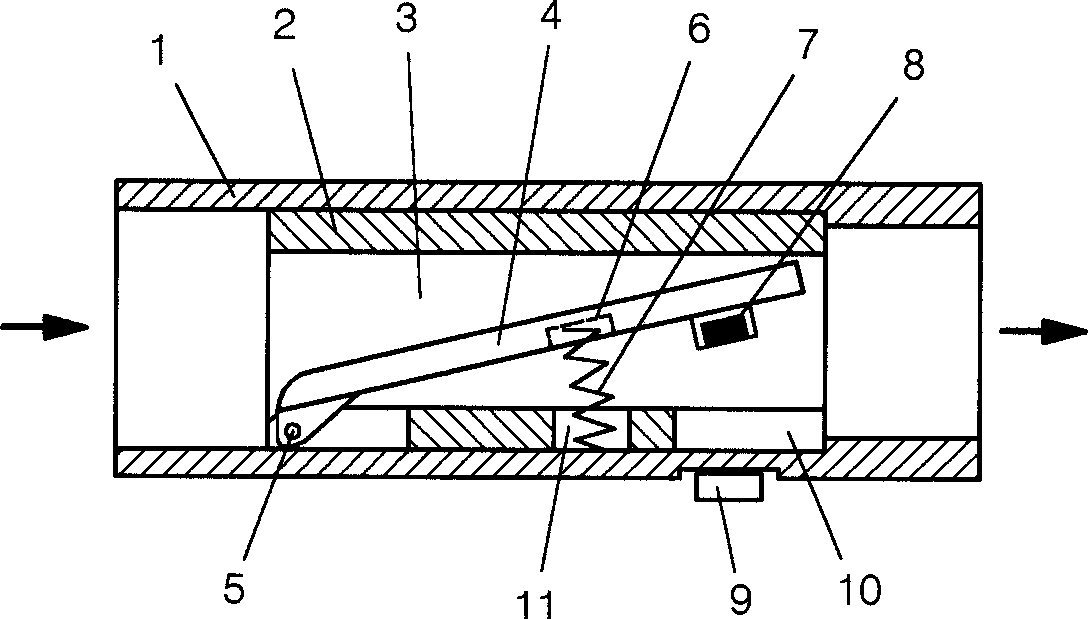
[0048] see Figure 1 to Figure 14 .
[0049] The inclined plate flow sensor includes a housing 1 . A fixed measuring tube 2 is installed inside the housing 1 , and the measuring tube 2 is hollow as a measuring flow channel 3 . The measuring channel 3 is equipped with a measuring plate 4, the upstream end of the measuring plate 4 is at the bottom of the upstream end in the inclined plate flow sensor, and the hinge shaft 5 is used to move on the bottom wall or side wall of the measuring tube 2 or on the casing 1 connect. A return spring 7 is installed between the measuring plate 4 and the measuring tube 2 or the housing 1 . Back-moving spring 7 can be the compression spring on the ventral side of the measuring board 4 or the extension spring on the back side, or the torsion spring at the flexible connection of the measuring board 4. Among them, the compression spring is the best, so the following examples are all in the form of compression springs. The spring form is describ...
Embodiment 2
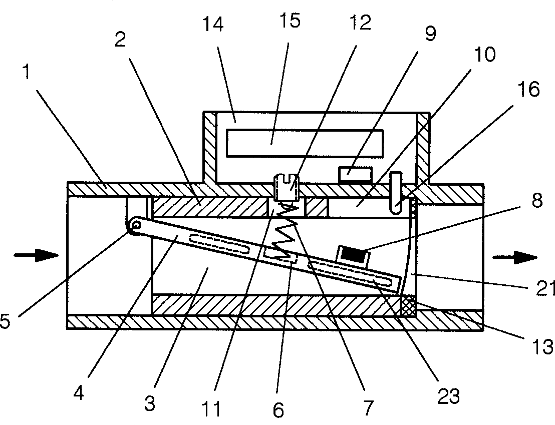
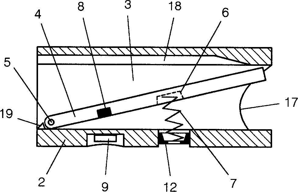
[0055] see Figure 2 ~ Figure 4 , Figure 15 ~ Figure 18 .
[0056] The basic structure and application examples of the present invention have been described above. But the requirements are diverse. Furthermore, in order to obtain a specific output characteristic curve, or to obtain a very good linear characteristic in a large range, people are still exploring. Although many samples of the inclined plate flow sensor without output characteristic correction or compensation have been tested, the accuracy and linearity have reached the practical level, which can meet the requirements of most applications. But we can still add special characteristic correction or compensation measures on this basis to meet the higher special requirements for output characteristic curves in some fields.
[0057] If under a certain flow value, the measuring plate 4 has an original deflection, then the sensor has an original output voltage value. "Original" here means the value before correction...
Embodiment 3
[0063] When the inclined plate flow sensor is installed upside down, if figure 2 As shown, that is, the flexible connection of the measuring plate 4 is above the measuring channel 3 . Due to the gravity of the measuring board 4, the return spring 7 and the magnet 8, a dead zone at the low end of detection will be caused. In order to solve the dead zone problem, a number of airtight cavities 23 can be made in the measuring plate 4, or a balance spring can be installed between the measuring plate 4 and the measuring tube 2 or the casing 1, so that the measuring plate 4 is suspended or quasi-suspended in the fluid medium. The suspension state achieves the purpose of eliminating the low-end dead zone. In view of the above, the measuring board 4 should be made of less dense plastics, such as ABS plastics with a density of 1.04-1.05. In addition, the inverted inclined plate flow sensor in which the measuring plate 4 is suspended by the sealed cavity 23 is not suitable for gas flo...
PUM
 Abstract
Description
Claims
Application Information