Eureka AIR delivers breakthrough ideas for toughest innovation challenges, trusted by R&D personnel around the world.

Optical disc recording method and device

A technology for optical disc recording and recording devices, applied in optical recording/reproducing/erasing methods, optical recording heads, optical recording systems, etc., can solve problems such as deterioration of recording signal quality and inability to achieve regular reproduction, and achieve recording jitter improvement, Effects of Record Quality Reduction

Inactive Publication Date: 2002-03-20
SONY CORP
View PDF0 Cites 5 Cited by
  • Summary
  • Abstract
  • Description
  • Claims
  • Application Information

AI Technical Summary

Problems solved by technology

[0008] If the recorded signal deteriorates in quality due to deformation of the pit shape or increased jitter, there is a risk that regular reproduction cannot be achieved

Method used


Image

  • Optical disc recording method and device
  • Optical disc recording method and device
  • Optical disc recording method and device

Examples


Embodiment Construction

[0033] Referring to the accompanying drawings, preferred embodiments of the present invention will be described in more detail.

[0034] The present invention is applied to structures such as the attached Image 6 An optical disc recording and / or reproducing apparatus 100 is shown.

[0035] Such as Image 6As shown, the optical disc recording and / or reproducing apparatus 100 is a disc drive of a mark length recording system, in which a CD-R (CD Recordable), that is, a write-once optical disc 1 is rotationally driven by a spindle motor 2 at CLV, and in which a laser is driven by The optical head 3 irradiates on the recording surface of the optical disc 1 to form pits to realize data recording and / or reproduction. Optical disc recording and / or reproducing apparatus 100 comprises the servo circuit 4 that is connected with spindle motor 2 and optical head 3, the recording pulse generation circuit 5 that is connected with optical head 3, the replay signal processing circuit 6 tha...


PUM


Abstract

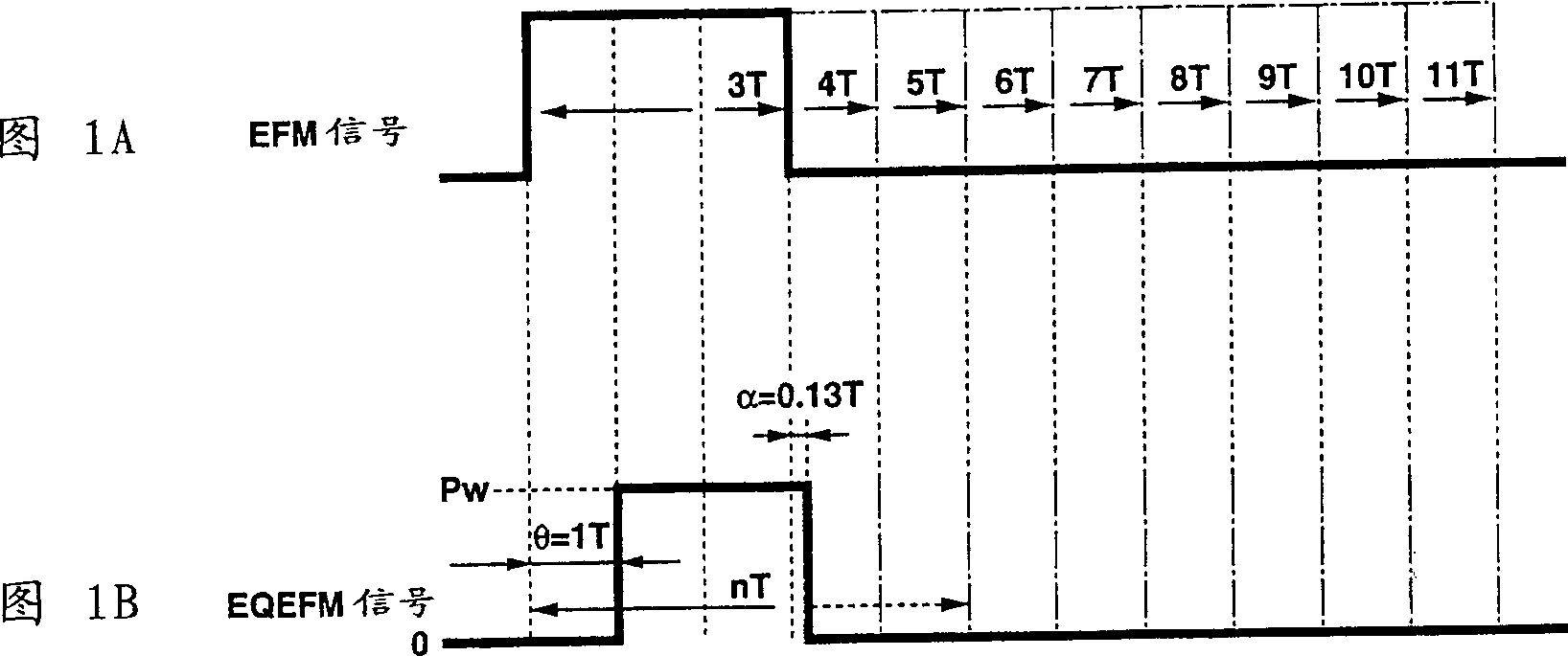
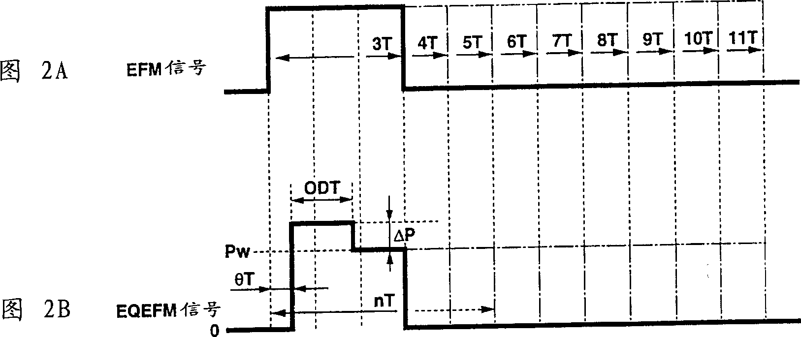
A method for recording on a write-once type optical disc. A laser light beam excited to light emission by a recording pulse having a pulse width corresponding to the length of a pit formed, with the recording power of substantially the leading end o the pulse being stepped over plural stages, is illuminated on a write-once type optical disc for recording. This enables recording with an optimal pit shape at a speed faster than a quadrupled speed, such as at an octupled speed or a duo-deca-tupled speed.

Description

technical field [0001] The invention relates to an optical disc recording method and device of a mark length recording system, wherein laser light is irradiated on the recording surface of the optical disc to form pits for information recording. In particular, it relates to methods and apparatus for recording optical discs for recording at speeds higher than quadruple speed, such as eight speed or twelve speed. Background technique [0002] Hitherto, when recording information on a recording medium such as an optical disc, according to the optical modulation system, thermal control is performed by pulsed emission of laser light in order to optimally form pits (marks) on the disc. In particular, the pulse waveform is set as the driving pulse for driving the laser, while the level (peak value) at each pulse period is also controlled to control the laser power and the laser power and laser irradiation period. [0003] For example, in an optical recording an...

Claims


Application Information

Patent Timeline
IPC IPC(8): G11B7/0045G11B7/126
CPCG11B7/00451G11B7/0045G11B7/00456G11B7/126G11B7/127G11B19/28G11B20/1496G11B2220/218G11B2220/2537
Inventor 佐佐木敬森敦司盛一宗利番场光幸
Owner SONY CORP
Why Eureka
Eureka Blog
Learn More