Recording medium, recording and reproducing method and recording and reproducing device
A technology for recording media and recording areas, applied in optical recording/reproducing/erasing methods, optical recording carriers, optical recording carrier manufacturing, etc., capable of solving problems such as servo signals and adverse effects of recording signals
- Summary
- Abstract
- Description
- Claims
- Application Information
AI Technical Summary
Problems solved by technology
Method used
Image
Examples
example 1
[0218] In this example, a light-transmitting substrate 1 made of polycarbonate resin having a diameter of 120 nm was provided. The selection range of the thickness of the light-transmitting substrate 1 is as follows: as long as the change of the transmittance and reflectance of the light-transmitting substrate 1 can be detected. Here, the selected thickness of the light-transmitting substrate 1 is 0.6 mm.
[0219] The following is the correlation between wavelength and transmission coefficient measured by two samples, one obtained after irradiating the light-transmitting substrate with ultraviolet rays from a UV lamp for 110 minutes, and the other after irradiating the light-transmitting substrate with ultraviolet rays1 got before. In FIG. 19, a solid-line curve 61 shows a correlation between wavelength and transmittance corresponding to a sample obtained before light-transmitting the substrate 1 with ultraviolet radiation. In FIG. 19, a dotted line curve 62 shows a correlat...
example 2
[0230] In this example, recording of information is carried out by selectively irradiating the light-transmissive substrate 1 with ultraviolet rays.
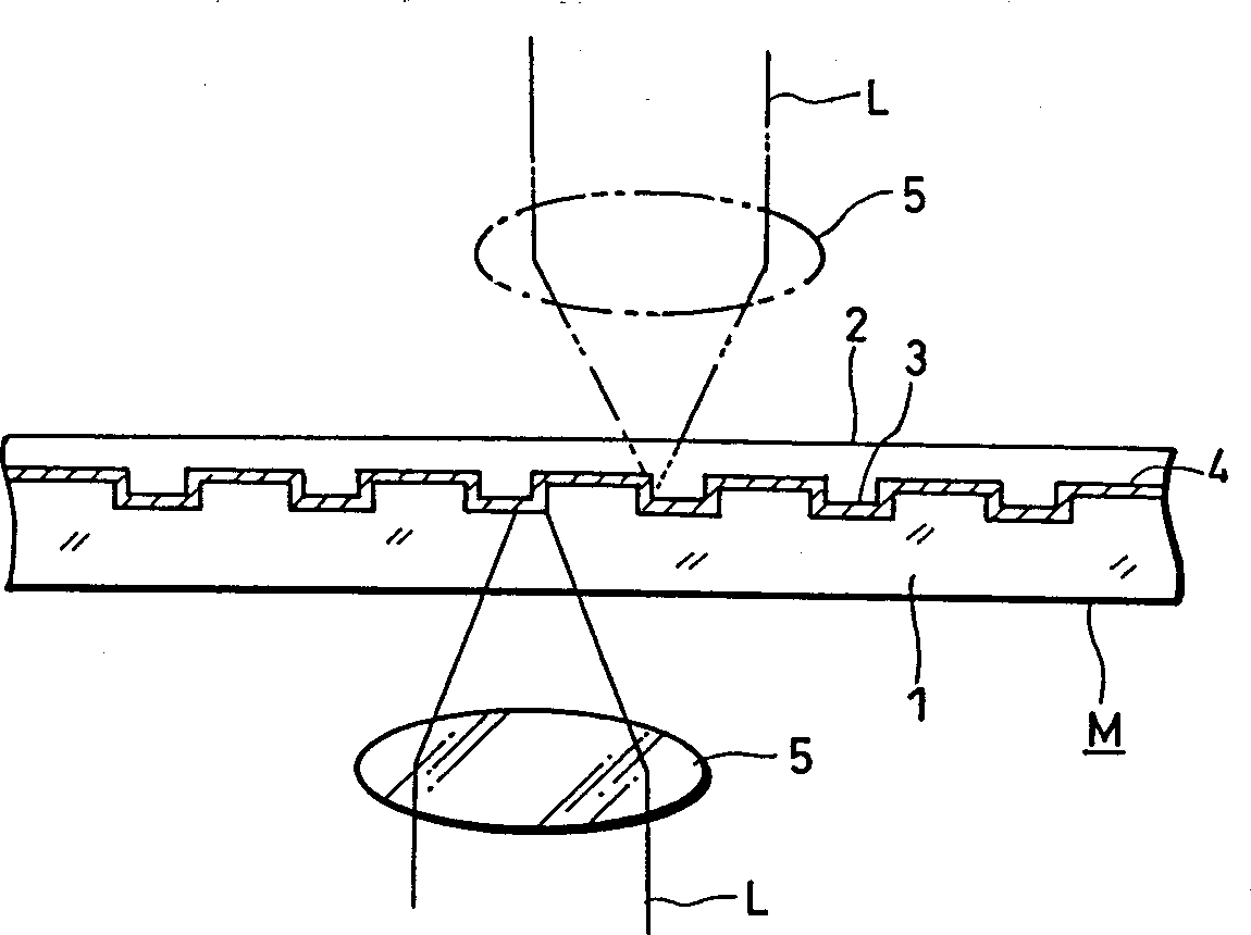
[0231] In particular, in this case, a light-transmitting substrate made of polycarbonate resin with a diameter of 120 mm was used, and in the design of the substrate, formed such as figure 1 Very small bumps shown. Moreover, in this case, the thickness of the substrate 1 can be selected in the following range: as long as changes in the transmittance and reflectance of the substrate 1 can be detected. Here, the selected thickness of the substrate 1 is 0.6 mm.
[0232] On one main surface of said light transmissive substrate 1, grooves including four memory areas having a track pitch of 0.40 µm to 0.36 µm and a minimum variation of 0.02 µm are formed.
[0233] In actual design, needless to say, pit marks and wobble grooves for reading addresses and the like may also be formed on one main surface of this light-transmitting substr...
example 3
[0240] In this Invention Example 3, referring to Invention Example 2 as described above, since information can be recorded on the light-transmitting substrate 1 by selectively irradiating an arbitrary position of the light-transmitting substrate 1 with ultraviolet rays, it is possible to The light-transmitting substrate 1 is selectively irradiated, information is recorded B to the light-transmitting substrate 1, and the recorded information B is reproduced using the reproducing apparatus according to the present invention.
[0241] Also in this case, as described above, there is provided a light-transmitting substrate 1 having a diameter of 120 mm. Still in this case, although the selection range of the thickness of the light-transmitting substrate 1 is as follows: as long as the change of the transmission coefficient and the reflection coefficient can be detected, but here, the thickness of the selected light-transmitting substrate 1 is 0.6 mm.
[0242] When ultraviolet rays...
PUM
| Property | Measurement | Unit |
|---|---|---|
| wavelength | aaaaa | aaaaa |
| wavelength | aaaaa | aaaaa |
| wavelength | aaaaa | aaaaa |
Abstract
Description
Claims
Application Information
 - R&D
- Intellectual Property
- Life Sciences
- Materials
- Tech Scout
- Unparalleled Data Quality
- Higher Quality Content
- 60% Fewer Hallucinations
Browse by: Latest US Patents, China's latest patents, Technical Efficacy Thesaurus, Application Domain, Technology Topic, Popular Technical Reports.
© 2025 PatSnap. All rights reserved.Legal|Privacy policy|Modern Slavery Act Transparency Statement|Sitemap|About US| Contact US: help@patsnap.com


