Sealing structure of cabin for building machinery

A technology of construction machinery and sealing structure, which is applied in the direction of construction, mechanical equipment, connecting components, etc., can solve the problems of unsealable, noise or dust intrusion, and cannot be reliably prevented, and achieve the effect of improving assembly and preventing intrusion

Inactive Publication Date: 2002-04-17
KOMATSU LTD
View PDF0 Cites 11 Cited by
  • Summary
  • Abstract
  • Description
  • Claims
  • Application Information

AI Technical Summary

Problems solved by technology

[0005] But when Figure 5 In the grommet 50 of the existing structure described in , when the hydraulic hose etc. The diaphragm 53 is turned up, and there will always be a gap in the peripheral part of the inserted hydraulic hose, etc., resulting in the problem of noise or dust entering through the gap.
[0006] On the other hand, in the technology disclosed in Utility Model No. 254175, which is cited as the prior art related to the p

Method used


Image

  • Sealing structure of cabin for building machinery
  • Sealing structure of cabin for building machinery
  • Sealing structure of cabin for building machinery

Examples


Embodiment Construction

[0017] Hereinafter, specific details of the sealing structure of the construction machinery cab of the present invention will be described with reference to the accompanying drawings.

[0018] The embodiment will be described.

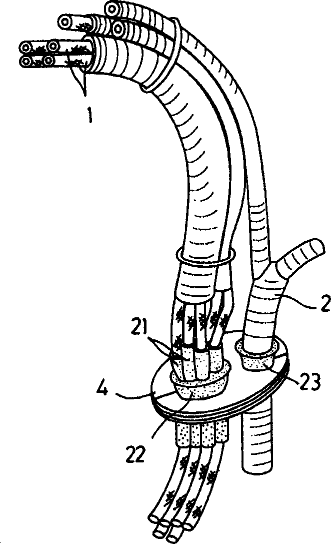
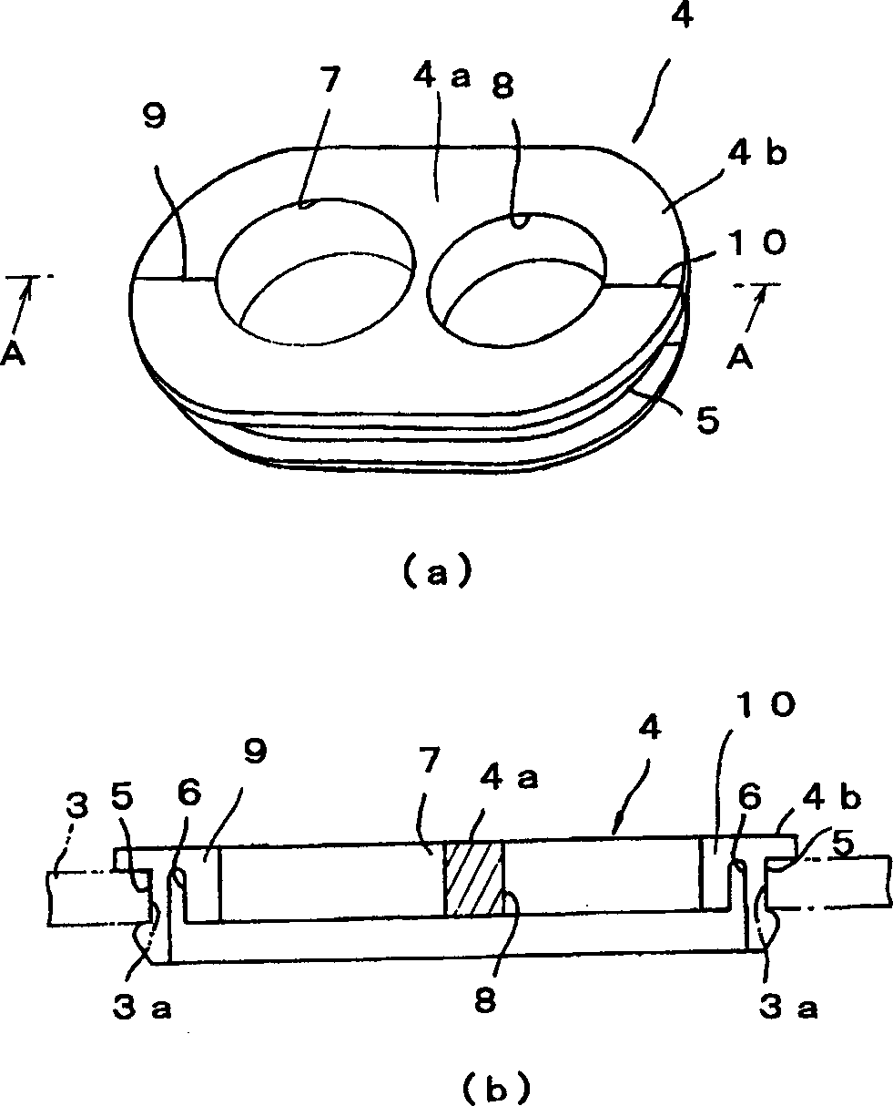
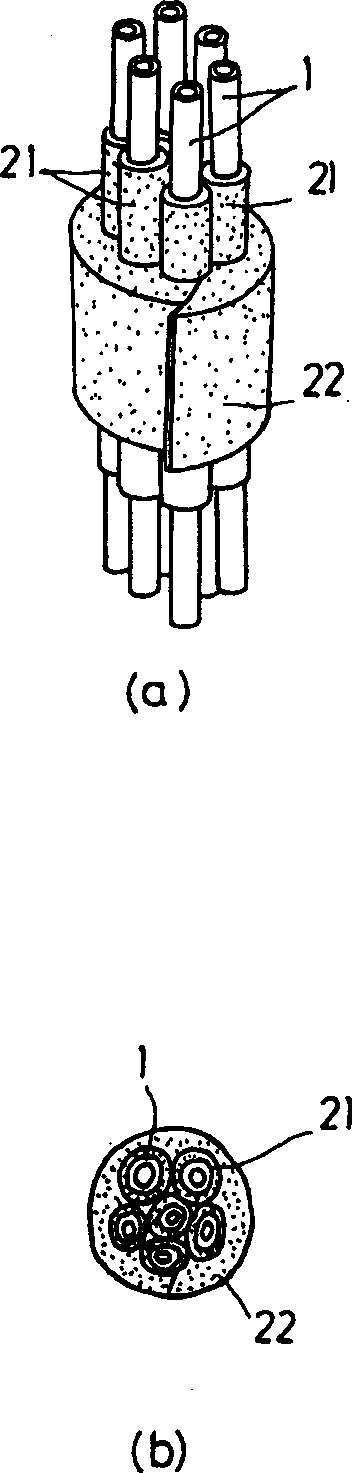
[0019] figure 1 A perspective view showing a cab sealing structure according to an embodiment of the present invention applicable to a hydraulic excavator, figure 2 It is the perspective view (a) of the eyelet used in the mechanism of this embodiment and its A-A sectional view (b), image 3 (a), (b) are views showing the sealing structure of this embodiment.

[0020] The sealing structure of the present embodiment is related to when several (six in the case of this embodiment) oil pressure hoses (PPC hoses) 1 and one electrical wiring harness 2 are passed through the ground of the cab. The sealing structure of the control lever installed in the cab of the hydraulic excavator includes an eyelet 4 that is engaged with and fixed to a through-hole 3 a...


PUM


Abstract

A sealing structure of cabin for building machinery can surely prevent the intrusion of noise or dust through a slit formed in a grommet or the clearance of adjacent hoses in a bundle of hydraulic hoses or the like. Hydraulic hoses are inserted to cylindrical seal members one by one. In the state where a plurality of the hydraulic hoses after insertion is bundled, the circumferential part thereof is retained by a tape-like seal member and inserted to an insert hole provided in the grommet.

Description

technical field [0001] The present invention relates to a sealing structure for a construction machine cab used in a construction machine such as a hydraulic excavator. Background technique [0002] Generally, in a construction machine such as a hydraulic excavator, a hydraulic hose, an electric harness, and the like extending from an operating lever in the cab are piped or wired to the outside while penetrating the floor and a partition. In this case, a through hole is formed in the ground or the like, and an eyelet is fitted in the through hole to hold the above-mentioned hydraulic hose or the like. [0003] Figure 5 (a) and Figure 5 (b) Respectively represent the top view and the C-C cross-sectional view of the widely used eyelet. As shown in the figure, the structure of the conventional grommet 50 is composed of a grommet body 52 having a groove 51 on the outer periphery that engages with a through hole formed on the ground, and a grommet body 52 that blocks the gromm...

Claims


Application Information

Patent Timeline
IPC IPC(8): E02F9/00B60R16/02B60R16/08E02F9/16F16B2/22F16L5/02
CPCE02F9/16
Inventor 西坂好夫水野浩之出村哲也
Owner KOMATSU LTD
Why Eureka
Try Eureka