Element mounting system and mounting method

A technology for installation systems and installation devices, which is applied in the direction of electrical components, electrical components, printed circuit components, etc.

Inactive Publication Date: 2002-05-22
PANASONIC CORP
View PDF0 Cites 36 Cited by
  • Summary
  • Abstract
  • Description
  • Claims
  • Application Information

AI Technical Summary

Problems solved by technology

[0007] However, so far, it is not possible to understand the deterioration state of some parts of such a mechanism with clear indicators. Only skilled operators find any abnormality in the operating state of the device to judge whether it is a precursor of component deterioration and decide w

Method used


Image

  • Element mounting system and mounting method
  • Element mounting system and mounting method
  • Element mounting system and mounting method

Examples


Embodiment Construction

[0035] Embodiments of the present invention will be described below with reference to the drawings.

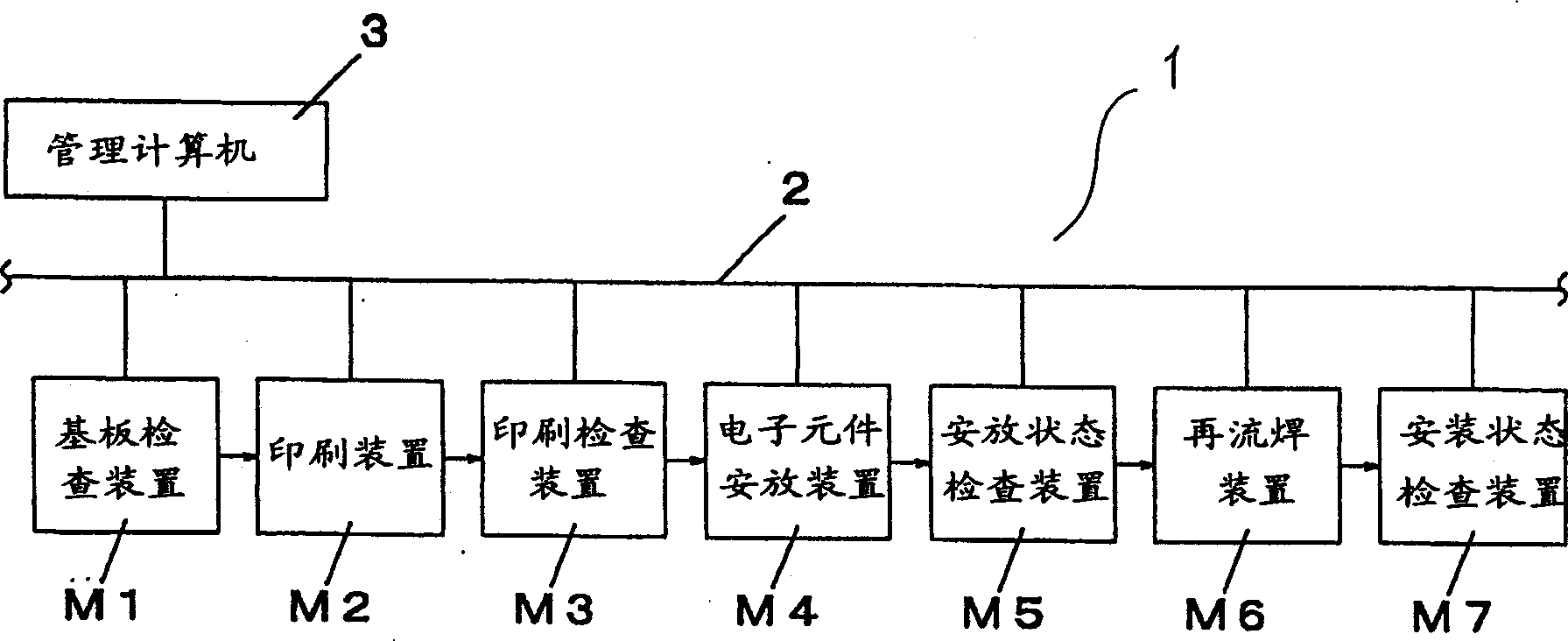
[0036] figure 1 Shown is a block diagram of the composition of the component mounting system in the embodiment of the present invention. First refer to figure 1 , the configuration of the component mounting system in this embodiment will be described. exist figure 1 Among them, this mounting system is constituted as follows, which includes substrate inspection device M1, printing device M2, printing inspection device (first inspection device) M3, component placement device M4, placement state inspection device (second inspection device) M5, and Each component mounting device of the flow soldering device (welding device) M6 and the mounting state inspection device (third inspection device) M7 is connected to form a component mounting line 1, and then the component mounting line 1 is connected with the communication network 2, and through the management computer 3 Control th...


PUM


Abstract

A component mounting system which includes a printer for printing solder on electrodes formed on a board; a first inspection unit for detecting positions of printed solder and outputting solder position detection results; a component mounting unit for picking up components from a component feeder carriage and placing the components on the board using mounting heads; a second inspection unit for inspecting positions of the components placed and outputting component position detection results; a soldering unit for soldering the components onto the board by heating and melting solder; and a main controller for updating at least a control parameter for controlling the printer operation or a control parameter for the component mounting unit operation based on at least the solder position detection results or component position detection results. The above configuration enables the accurate and efficient quality control throughout the mounting process.

Description

technical field [0001] The present invention relates to a component mounting system and a mounting method for mounting components such as electronic components on a substrate, for example. Background technique [0002] In recent years, with the miniaturization of electronic components such as semiconductors and the high density of mounting, the positional accuracy when mounting components on substrate electrodes is also improving. For example, in small devices such as mobile phones, which have been widely spread in recent years, many components with a small size of about 0.6 mm×0.3 mm are mounted at a narrow pitch of about 0.1 mm. When mounting such components, extremely high mounting position accuracy is required. [0003] When mounting components of such a small size as described above, special consideration is required for the management of the mounting quality. That is, in order to ensure the quality of the manufactured mounting substrate so that it can be used normall...

Claims


Application Information

Patent Timeline
IPC IPC(8): H05K1/02H05K3/00H05K3/12H05K13/04H05K13/08
CPCH05K3/1216H05K1/0269H05K13/08H05K13/0465H05K13/0413H05K3/0008H05K13/0817H05K13/083Y10T29/49002Y10T29/49131Y10T29/49144Y10T29/49826Y10T29/53052Y10T29/53091Y10T29/53178
Inventor 井上雅文冢本满早藤冈正人
Owner PANASONIC CORP
Why Eureka
Try Eureka