Balanced transmission shielded cable

A shielded cable, balanced technology, applied in the direction of power cables, communication cables, including electric control power cables, etc., can solve the problems of increased transmission loss, no impedance, difficult problems, etc.

Inactive Publication Date: 2002-06-05
JST MFG CO LTD
View PDF0 Cites 15 Cited by
  • Summary
  • Abstract
  • Description
  • Claims
  • Application Information

AI Technical Summary

Problems solved by technology

However, the distances from the wires of each twisted pair 31 to the shielded conductor 33 and the distances to the wires of other twisted pairs are not equal in the length direction of the cable, so there is no stable impedance.
Therefore, it is difficult to effectively reduce the crosstalk (crosstalk interference) between the twisted pair 31 for signal transmission.
[0006] On the othe

Method used


Image

  • Balanced transmission shielded cable
  • Balanced transmission shielded cable
  • Balanced transmission shielded cable

Examples


Embodiment Construction

[0019] Hereinafter, preferred embodiments of the present invention will be described with reference to the accompanying drawings.

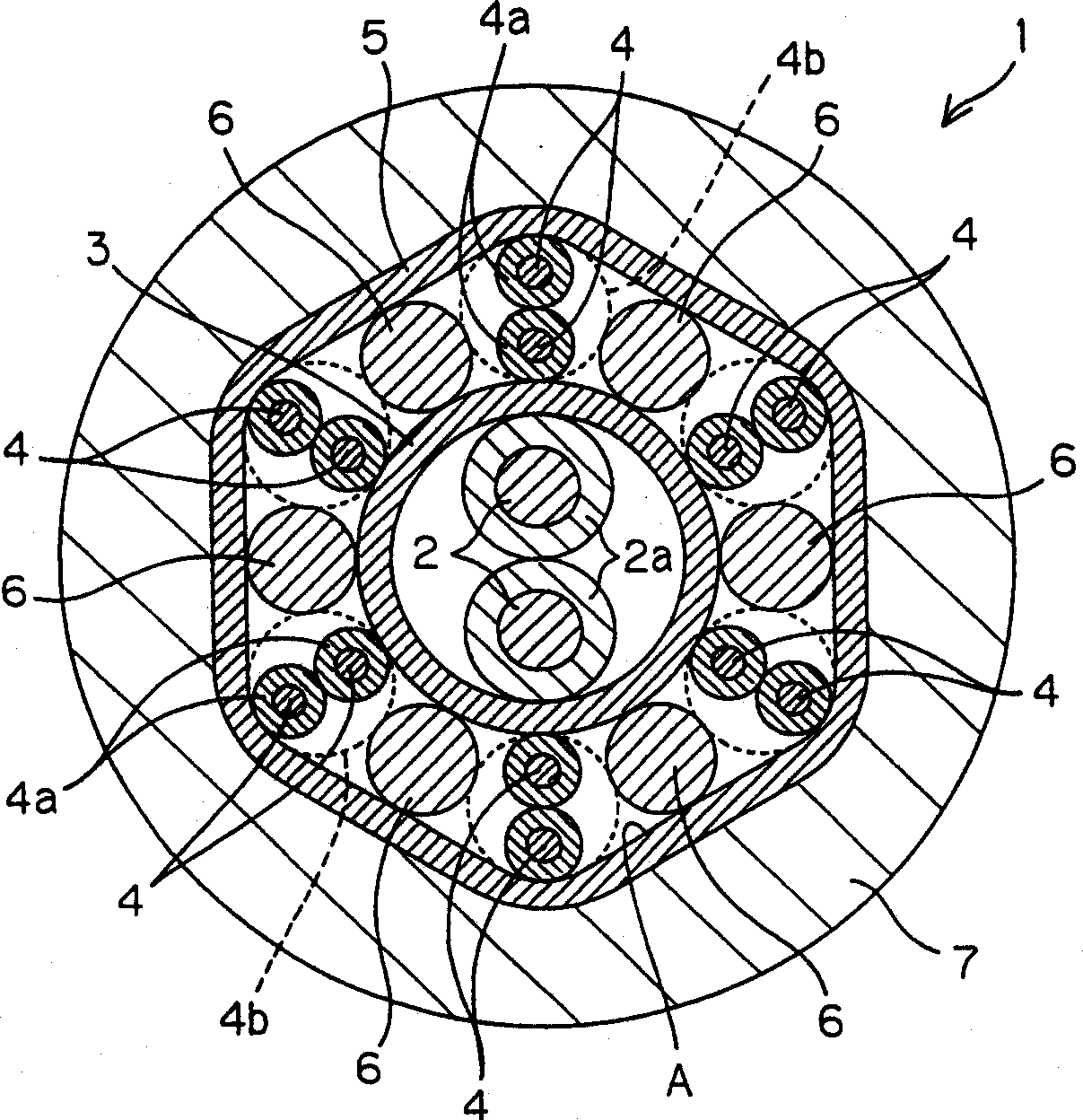
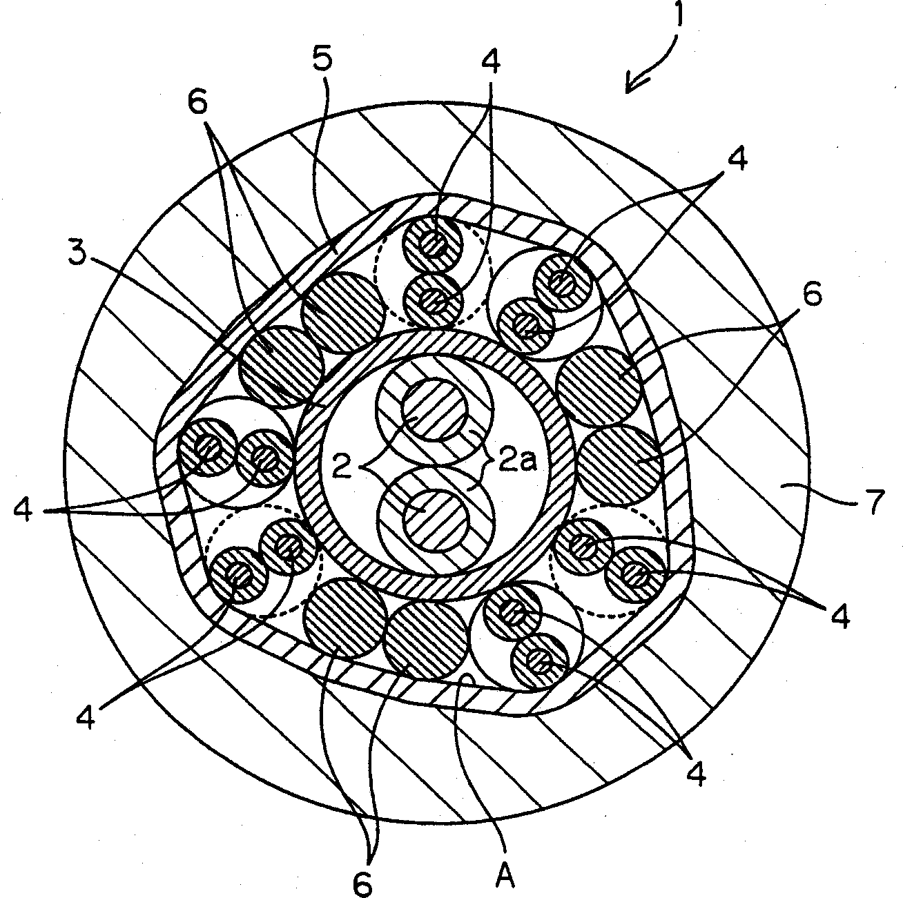
[0020] figure 1 It is a cross-sectional view of a balanced transmission type shielded cable for LVDS transmission according to Embodiment 1 of the present invention. like figure 1 As shown, the present shielded cable 1 has a power line 2 arranged in the center of the cross section, and the inner shield conductor 3 surrounds the power line 2 . The power cord 2 is formed by twisting a pair of wires covered with an insulator 2a at a predetermined helical interval, and the outer peripheral shape of the power cord 2 subjected to such an insulation coating treatment can be used on the inner peripheral surface of the inner shield conductor 3. is represented by the distorted cross-sectional shape shown by the double circle on .

[0021] A plurality of pairs of unshielded twisted pairs 4 are arranged in a ring shape around the inner shielded conductor...


PUM


Abstract

A balanced transmission shielded cable comprising an inner conductive shield (3) and an outer conductive shield (5) surrounding the inner conductive shield (3). In an annular region (A) defined between both shields (3, 5), unshielded twisted pairs (4) for signal transmission and shielded drain lines (6) are alternately disposed in annular array. The shielded drain lines (6) contact both shields (3, 5) and are led outside and grounded. Both shields (3, 5) surrounding the twisted pairs (4) and the shielded drain lines (6, 6) keep a substantially uniform distance with respect to conductive lines constituting the twisted pairs (4).

Description

technical field [0001] The invention relates to a balanced transmission shielded cable, which includes an unshielded twisted pair for transmitting multi-channel signals, for example, for signal transmission between circuit boards of electronic equipment. Background technique [0002] As a transmission line for transmitting signals, shielded cables transmit signals by using multiple wires that are physically separated and electromagnetically insulated throughout their length, such as cables used in local area networks (LAN) and as A cable used for internal and external connection cables of a personal computer. It is hoped that such a cable can achieve a higher data transmission speed (for example, a transmission speed of more than 10 Mbps to 650 Mbps). [0003] Therefore, people have proposed a transmission method of using unshielded twisted pair wires (unshield twisted pairwires) to transmit low voltage differential signaling (Low Voltage Defferential Signaling, hereinafter...

Claims


Application Information

Patent Timeline
IPC IPC(8): H01B11/02H01B9/00H01B11/06H01B11/08H01B11/10
CPCH01B11/1091H01B11/08H01B9/003H01B11/02
Inventor 保坂泰司竹乃下浩
Owner JST MFG CO LTD
Why Eureka
Try Eureka