
Precise electronic watch with analog display

A technology for simulating electronics and chronographs, applied to mechanical devices for time indication, measurement of electrical unknown time intervals, measurement of electromechanical unknown time intervals, etc.

Inactive Publication Date: 2002-07-03
ETA SA MFG HORLOGERE SUISSE
View PDF3 Cites 9 Cited by
  • Summary
  • Abstract
  • Description
  • Claims
  • Application Information

AI Technical Summary

Problems solved by technology

[0004] However, this solution has certain disadvantages

Method used


Image

  • Precise electronic watch with analog display
  • Precise electronic watch with analog display
  • Precise electronic watch with analog display

Examples


Embodiment Construction

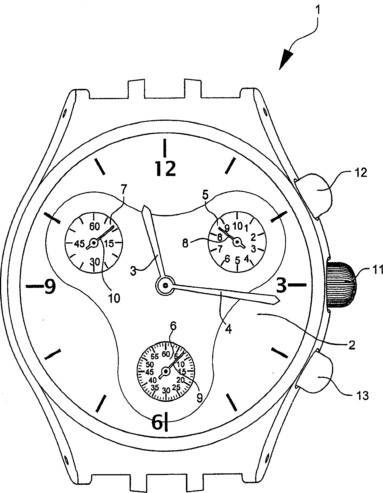
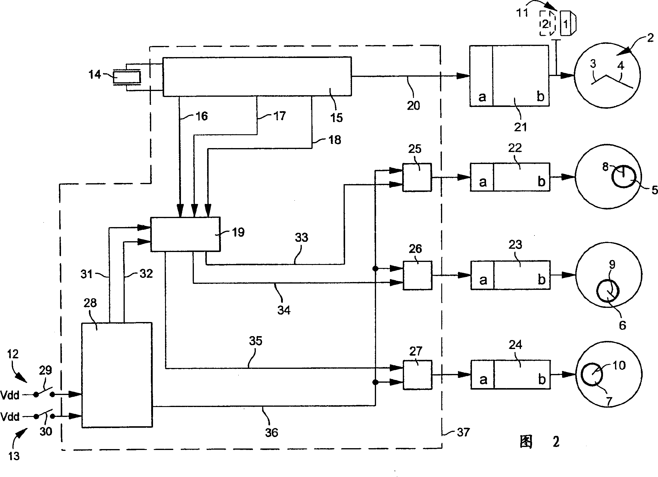
[0022] A chronograph 1 according to a preferred embodiment of the invention comprises a disc 2 for indicating the current time by means of a hand 3 indicating hours and a hand 4 indicating minutes. The disc 2 also includes three small discs 5, 6 and 7 associated with three small hands 8, 9 and 10 for indicating the measured time. These small disks are located near the edge of disk 2 at 2 o'clock, 6 o'clock and 10 o'clock respectively. They represent measured tenths of a second, measured seconds, and measured minutes, respectively.

[0023] The watch also includes a crown 11 and two pushers 12 and 13 . In a preferred embodiment, the crown 11 enables the position of the hands 3 and 4 to indicate the current time to be adjusted or set by using a known time-setting device of a sliding cannon pinion. The two buttons 12 and 13 are of the type referred to in European Patent Application No. 00202007. They make all these chronometric functions accessible to the user of the watch thr...


PUM


Abstract

An electronic chronograph watch (1) with an analogue display wherein the measured times are displayed on small dials (5, 6, 7) located on the periphery of the main dial (2). The measured times are displayed by small hands (8, 9, 10) each driven by a motor. The watch (1) includes a stem-crown (11) used to adjust the position of the hands (3, 4) indicating the current time via conventional mechanical means. The watch further includes at least two push-buttons (12, 13) which, when manipulated, allow access to all the functions of the chronograph part, including the function of adjusting the rest position of the chronograph hands (8, 9, 10).

Description

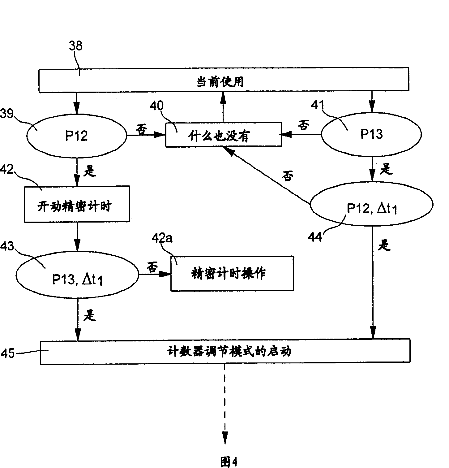
Background of the invention [0001] The invention relates to an electronic analog chronograph comprising: at least one first motor driving a hand showing the current time; at least one second motor driving at least one chronograph hand; a crown for adjusting or setting the current time (Stern- cravn) and two buttons for controlling the chronograph functions, the watch includes two operating modes for the chronograph, the first is the current operating mode, where the chronograph completes start, stop, reset and intermediate times Measuring function, the second mode of operation is the mode of adjusting the reset position of the chronograph hands. [0002] A well known problem with such watches is that the additional hands which perform the chronometer function can drift from zero when they normally indicate their reset position. This usually occurs during manufacture prior to placement of the battery, or later when the battery is changed or simply removed. [0003] Solutions ...

Claims


Application Information

Patent Timeline
IPC IPC(8): G04C3/00G04C9/08G04F7/08G04F8/02G04F10/00
CPCG04F7/08G04C3/146G04F10/00G04C3/005
Inventor B·维斯布罗德R·马奎斯S·克劳德
Owner ETA SA MFG HORLOGERE SUISSE
Learn More