Channel dispatch in optical router

A router, unscheduled technology, applied in the field of optical switching, can solve the problem of unsatisfactory optical network

Inactive Publication Date: 2002-07-24
ALCATEL LUCENT SAS
View PDF1 Cites 5 Cited by
  • Summary
  • Abstract
  • Description
  • Claims
  • Application Information

AI Technical Summary

Problems solved by technology

[0007] Previous optical networks for directly processing end-to-end user data channels are less than satisfactory

Method used


Image

  • Channel dispatch in optical router
  • Channel dispatch in optical router
  • Channel dispatch in optical router

Examples


Embodiment Construction

[0039] The present invention can be best understood with reference to Figures 1-26 of the accompanying drawings, in which the same reference numerals are used to designate the same parts.

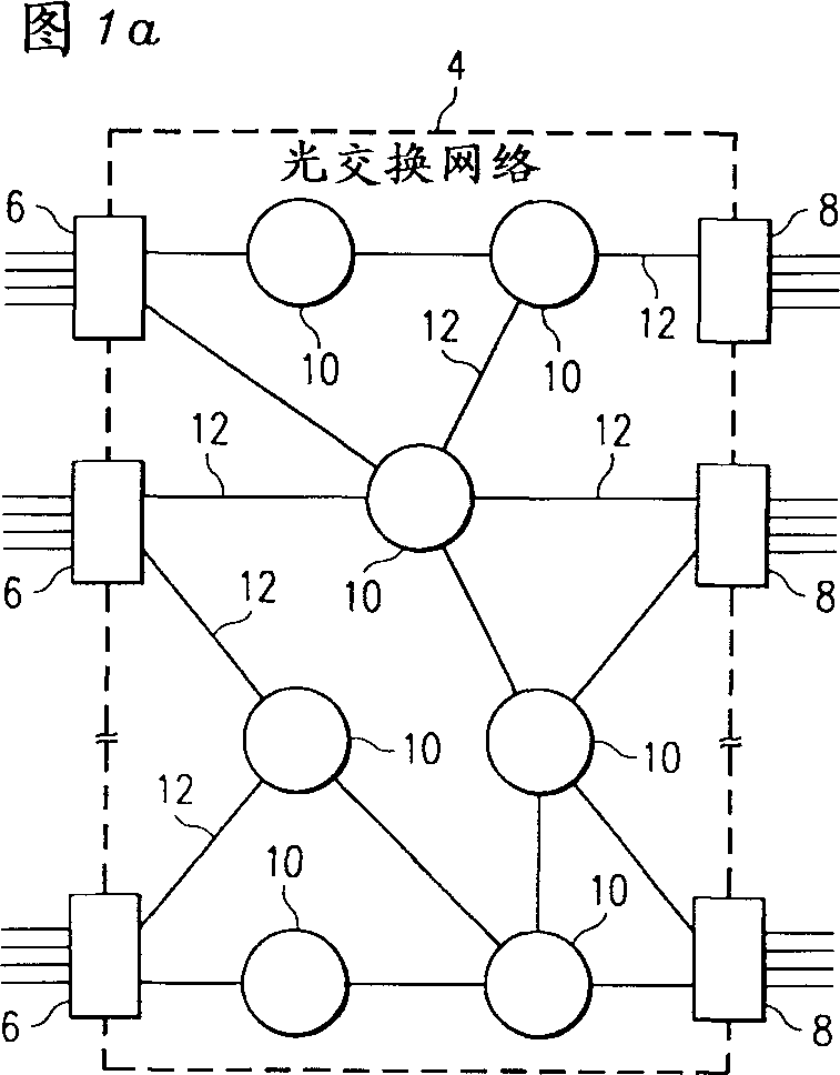
[0040] FIG. 1 a shows a general block diagram of an optical burst switched network 4 . Optical burst switching (OBS) network 4 includes a plurality of electronic ingress-port routers 6 and a plurality of egress-port routers 8 . These ingress routers 6 and egress routers 8 are connected to a plurality of core optical routers 10 . The ingress router 6 , the egress router 8 and the core router 10 are connected by an optical link 12 . Each optical fiber is capable of carrying multiple channels of optical data.

[0041] In operation, a data subframe (or simply "burst") of optical data is the basic data block to be sent over the network 4 . The ingress router 6 and the egress router 8 are responsible for burst combining and splitting functions and serve as an old-fashioned interface between th...


PUM


Abstract

The present invention relates to a unified associated memory of data channel despatcher in optical routers. An optical switch network (4) includes optical routers (10), which route information in optical fibers (12). Each fiber carries a plurality of data channels (20), collectively a data channel group (14), and a control channel (16). Data is carried on the data channels in data bursts and control information is carried on the control channel (18) in burst header packets. A burst header packet includes routing information for an associated data burst (28) and precedes its associated data burst. Parallel scheduling at multiple delays may be used for faster scheduling. In one embodiment, unscheduled times and gaps may be processed in a unified memory for more efficient operation.

Description

[0001] Related Application Cross Reference [0002] This application claims the filing date of co-pending U.S. Provisional Application Serial No. 60 / 257,884, filed December 22, 2000 by Zheng et al., entitled "Unified Associative Memory for Data Channel Scheduler in Optical Routers" technical field [0003] The invention relates to the field of telecommunications, in particular to an optical switching method and equipment. Background technique [0004] Recently, the data traffic volume in the network, especially the Internet, has increased dramatically, and with the increase of users and the adoption of new services requiring wide bandwidth, the data traffic volume will continue to increase. The increase in Internet traffic requires networks with high capacity routers in order to be able to send data packets of variable length. One option is to use optical networks. [0005] Emerging dense wavelength division multiplexing (DWDM) technology improves the bandwidth problem by ...

Claims


Application Information

Patent Timeline
Patent Type & Authority Applications(China)
IPC IPC(8): H04B10/00H04B10/27H04L12/46H04L12/56H04Q11/00
CPCH04Q2011/0039H04Q2011/0064H04L49/15H04L49/357H04Q11/0066H04L12/5693H04Q2011/0024H04Q2011/005H04L12/5601H04L47/562H04Q2011/0069H04L49/00H04Q2011/002H04Q11/0005H04L47/50
Inventor 熊一俊郑斯清
Owner ALCATEL LUCENT SAS
Why Eureka
Try Eureka