
Converter controlled power generator

A technology of inverters and generators, which is applied in the direction of controlling generators, controlling generators through magnetic field changes, and controlling systems, etc., and can solve problems such as output power decline

Inactive Publication Date: 2002-08-14
HONDA MOTOR CO LTD
View PDF1 Cites 5 Cited by
  • Summary
  • Abstract
  • Description
  • Claims
  • Application Information

AI Technical Summary

Problems solved by technology

[0005] In addition, when it is desired to change the number of rotations to adjust the voltage generated by the generator, it can only be used in the range where voltage shortage will not occur in the low-speed area, that is, in the Figure 9 In the example, it can only be used at the number of revolutions that can exceed the target voltage V
On the other hand, since the characteristics of the overcurrent side exceeding the maximum output power are frequently used in the high-speed region, there is a problem that the output power inevitably decreases.

Method used


Image

  • Converter controlled power generator
  • Converter controlled power generator
  • Converter controlled power generator

Examples


Embodiment Construction

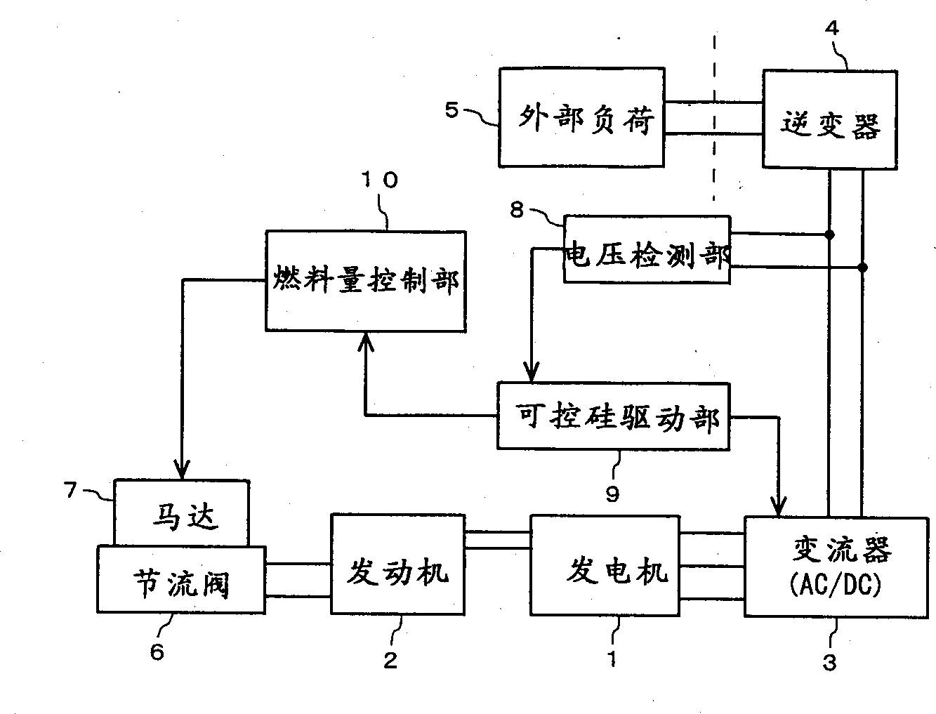
[0021] An embodiment of the present invention will be described in detail below with reference to the accompanying drawings. figure 1 is a functional block diagram showing an inverter-controlled engine. A permanent magnet multi-pole generator (hereinafter simply referred to as "generator") 1 is driven by an (internal combustion) engine 2 and generates multi-phase (typically 3-phase) alternating current. The generated alternating current is converted into direct current through full-wave rectification by the converter 3. The converter 3 is a rectifier formed by combining thyristors (generally semiconductor rectifying elements) as semiconductor rectifying elements into a bridge form. Circuit formation. This DC power is input to the inverter 4, and the inverter 4 supplies single-phase AC power of a commercial frequency (for example, 50 Hz) to the external load 5 connected to the output side. A stepping motor 7 is provided to adjust the opening of the throttle valve 6 of the en...


PUM


Abstract

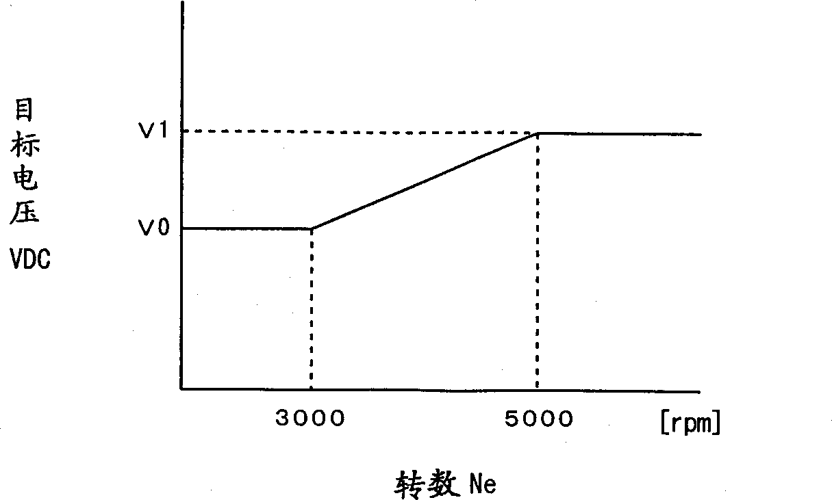
Disclosed is a converter controlled generator. The generator converts a direct current outputted from a converter constituted of semiconductor rectifying elements for rectifying an output of a magnet generator into an AC. The conduction of thyristors is determined by a thyristor drive unit to control the voltage output of the converter to a target voltage level. The target voltage level is set to a positive value corresponding to the speed of the generator. The target voltage level is lowered when the generator is operated at a lower speed range and elevated when at a higher speed range. Accordingly, the output of the magnetic generator is increased substantially in proportion to the speed.

Description

technical field [0001] The present invention relates to an inverter-controlled generator, and more particularly to an inverter control capable of operating the generator with good efficiency over a wide range of revolutions in the case where a permanent magnet generator is used as a generator type generator. Background technique [0002] An inverter is increasingly used in an engine generator used as an AC power supply unit to stabilize the output frequency. For example, as described in Japanese Patent Application Laid-Open No. 11-308896, an engine generator is used. In such an inverter-controlled generator, an engine connected to the generator is driven to generate AC power, which is converted into DC power, converted into AC power of a commercial frequency by an inverter, and output. In the inverter-controlled generator, since the output frequency is not related to the engine speed, by controlling the engine speed, it is possible to control the required output power, tha...

Claims


Application Information

Patent Timeline
IPC IPC(8): H02M5/458H02P9/04H02P9/30
CPCH02P9/04H02P9/305H02M5/4585
Inventor 清水元寿中村政史
Owner HONDA MOTOR CO LTD
Learn More