Apparatus for making metallic wire binding parts

A metal wire and binding technology, which is applied in the directions of binding, making rings from wires, and applications, can solve the problems of time-consuming, uneconomical production of small print volumes, etc., and achieve the effect of saving materials

Inactive Publication Date: 2002-08-28
HEIDELBERGER DRUCKMASCHINEN AG
View PDF4 Cites 9 Cited by
  • Summary
  • Abstract
  • Description
  • Claims
  • Application Information

AI Technical Summary

Problems solved by technology

Therefore, the production of small runs is uneconomical and requires a long time due to machine set-up

Method used


Image

  • Apparatus for making metallic wire binding parts
  • Apparatus for making metallic wire binding parts
  • Apparatus for making metallic wire binding parts

Examples


Embodiment Construction

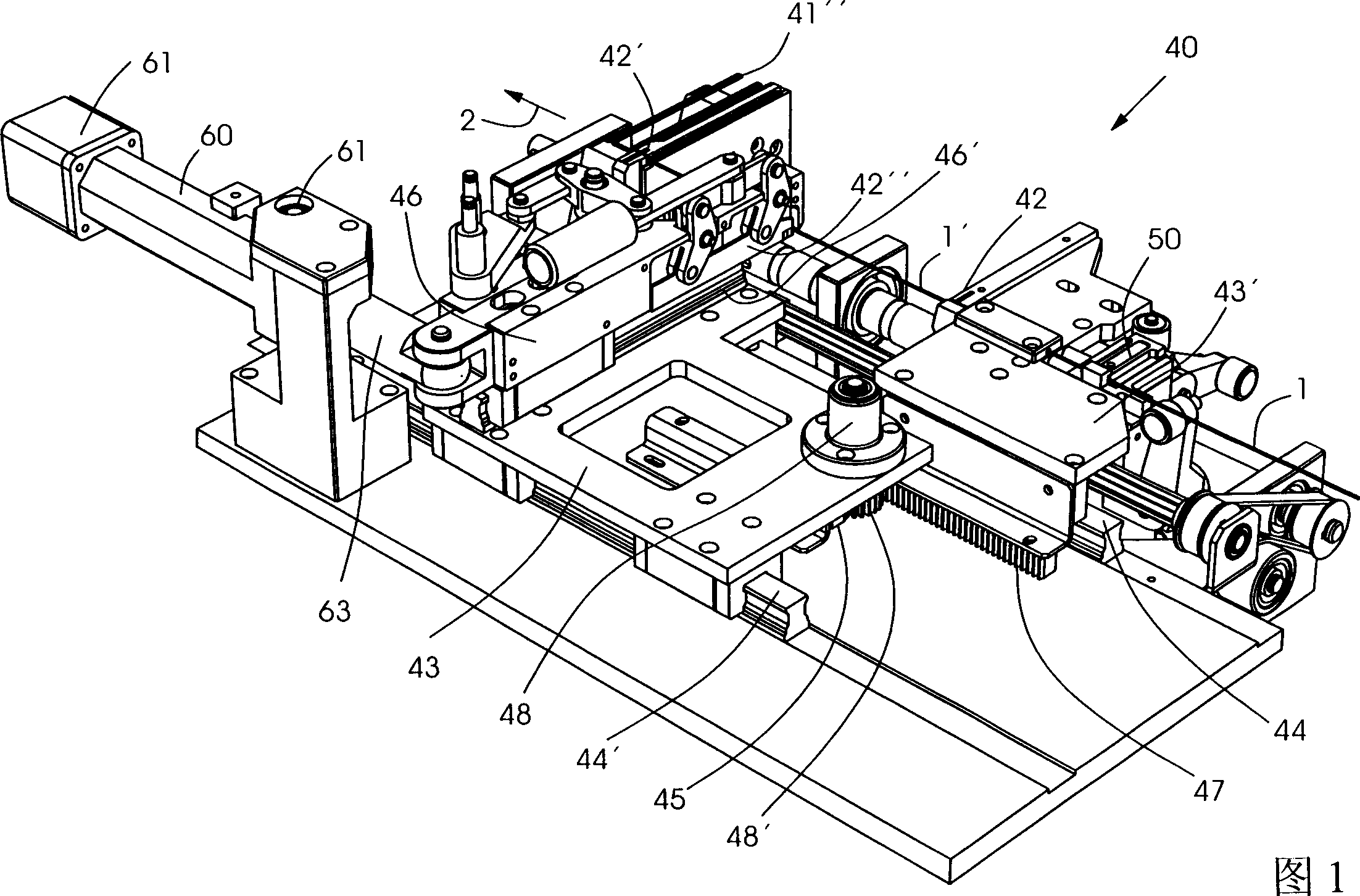
[0059] Figure 1 shows an inventive device, represented by symbol 40, for the flexible manufacture of wire binders for binding booklets of any size and thickness by means of a wire comb binder, in which only or The main building blocks of the invention are described. Other drives and / or guides and cams which are generally known and are required for the operation of the device are only schematically drawn or described in general form.

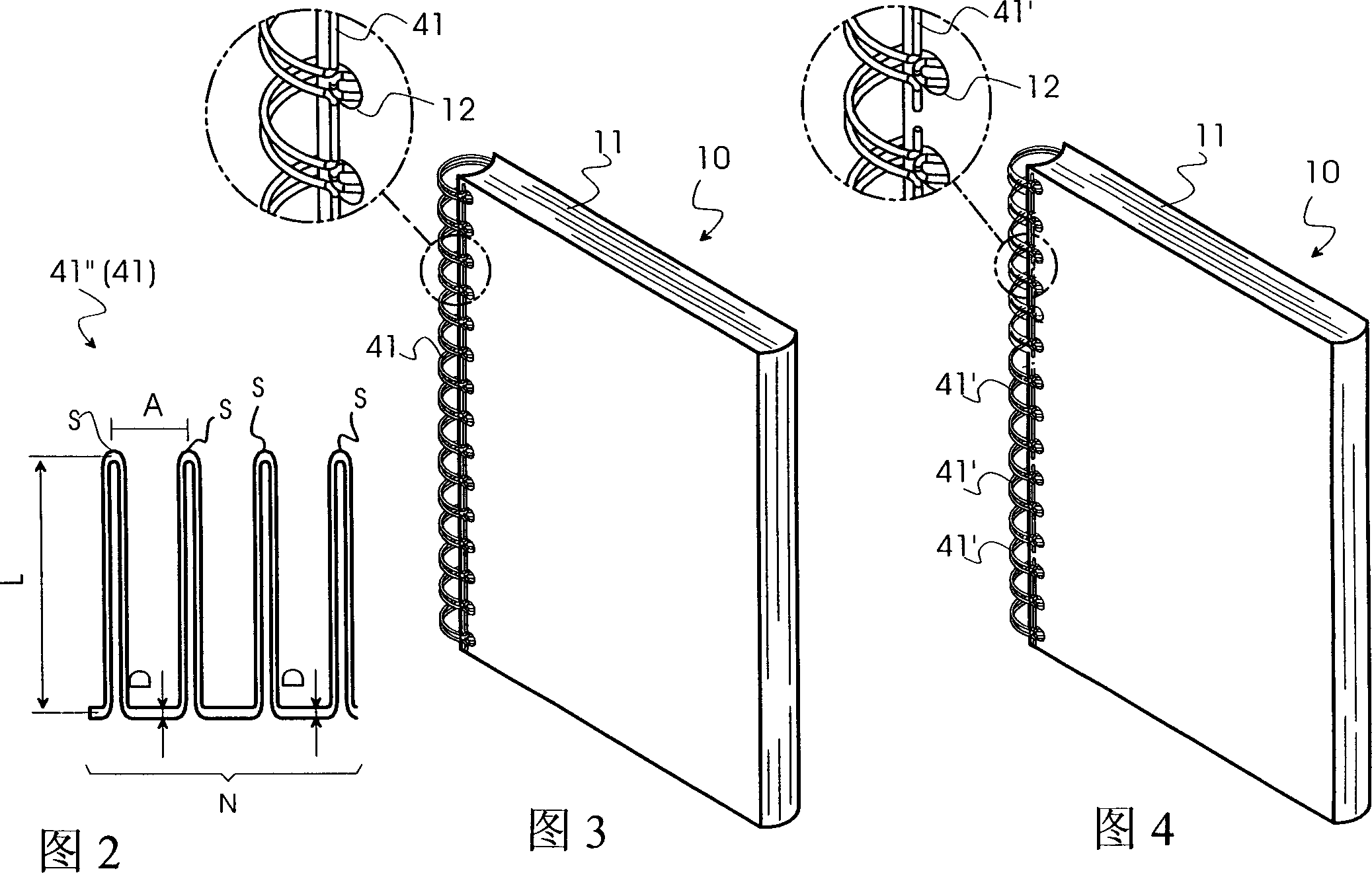
[0060] When there are more than two loops, the wire bindings 41, 41', 41", which are also referred to as wire plates 41", as shown in Figure 2, have a loop length of L, loop spacing of A, metal A loop S with a wire diameter D and a loop number N.

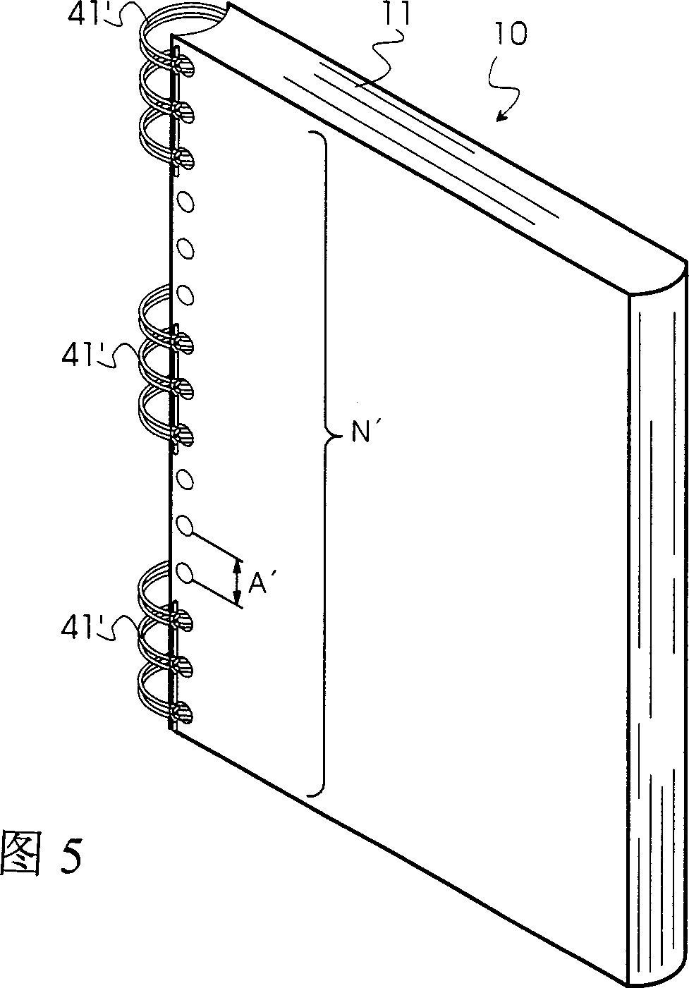
[0061] FIG. 3 shows a bound booklet 10 which has a continuous binding structure. A single binding structure is shown in FIG. 4, which consists of wire binding elements 41', which each have only a single loop and use a wire binding for each hole 12 in the printing carrier. Part 41'. FIG. 5 shows a w...


PUM


Abstract

The invention relates to a device for producing wire binders (41, 41', 41") for binding booklets of different sizes and thicknesses by means of a wire comb binder, wherein, The wire bindings (41, 41', 41") can be manufactured directly before binding according to the requirements thereof and the respective selected specifications and thicknesses of the booklets to be bound. Wire binders ( 41, 41′, 41″), the number of loops may correspond to the length of the largest booklet to be processed. No modification or adaptation of the device for manufacturing the wire binder (41, 41′, 41″) is required.

Description

technical field [0001] The invention relates to a device for producing wire binders of any size and thickness, of the type specified in the preamble of claim 1 . Background technique [0002] Devices of the above-mentioned type are generally used to produce wire binders which are used in binding devices by means of wire comb binders, in particular so-called wire-O TM A wire binder (registered trademark) loosely binds a booklet consisting of a plurality of printed pages. [0003] wire-O wire bindings are defined as wire loops spaced parallel to each other and having loop length L, loop spacing A and wire diameter D, and which are formed into wire-O by means of suitable closing means return line. [0004] Wire bindings are typically stored in a library for use with such binding devices to account for different binding requirements, such as booklet thickness and gauge, by loop length, loop spacing, etc. Devices for producing wire binders with different parameters such as loo...

Claims


Application Information

Patent Timeline
Patent Type & Authority Applications(China)
IPC IPC(8): B42F13/16B21D11/00B21F1/00B21F37/00B21F45/16B42B5/08
CPCB21F45/16
Inventor 马里奥·利奇
Owner HEIDELBERGER DRUCKMASCHINEN AG
Why Eureka
Try Eureka