Production method of composite bimetal pipe

A composite bimetallic and production method technology, applied in the production field of composite bimetallic pipes, can solve problems such as expensive production equipment and complex production process, and achieve the effects of wide application, simple production process and cost reduction

Inactive Publication Date: 2002-09-04
大连合生科技开发有限公司
2 Cites 32 Cited by

AI-Extracted Technical Summary

Problems solved by technology

[0005] The purpose of the present invention is to solve the technical problems of expensive production equipment and complex production proc...

Abstract

A production method of composite bimetal pipe includes the following steps: making surface treatment of internal pipe and external pipe: inserting internal pipe into external pipe, tight fitting to form composite pipe blank; seating the two ends of the said pipe blank with air and liquid in the internal pipe, and sealing the gap between the internal pipe and the external pipe, heating and diffusion annealing so as to obtain the invented product. Its production process is simple, and is applicable to various anticorrosion pipes.

Technology Topic

Image

  • Production method of composite bimetal pipe
  • Production method of composite bimetal pipe
  • Production method of composite bimetal pipe

Examples

  • Experimental program(1)

Example Embodiment

[0017] The specific embodiments of the present invention will be described below in conjunction with the drawings.
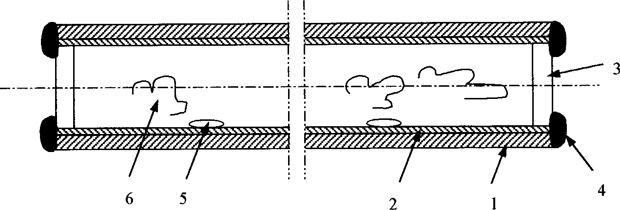
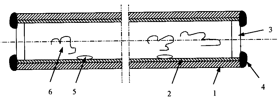
[0018] According to the mechanical performance requirements of the composite bimetallic pipe, carbon structural steel pipes with different carbon content are selected as the outer pipe 1. The outer tube of this embodiment is a 10-steel round tube with an outer diameter of 25 mm and a wall thickness of 2.5 mm. According to the requirements of corrosion resistance, choose different corrosion-resistant metal tubes as the inner tube 2. For the inner tube of this embodiment, a T2 round copper tube with an outer diameter of 19 mm and a wall thickness of 0.5 mm is selected. The inner diameter of the carbon steel tube is slightly larger than the outer diameter of the copper tube, which makes it easy to insert the copper tube into the steel tube.
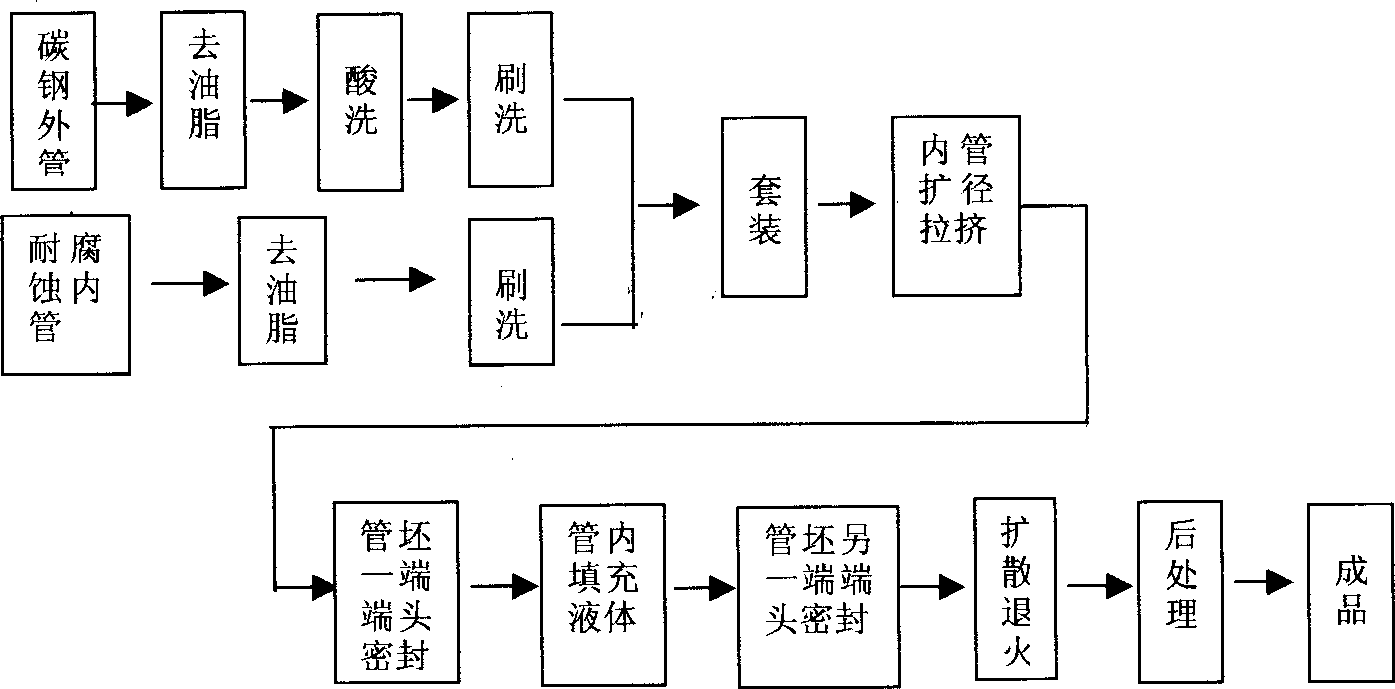
[0019] The production process of the embodiment of the present invention is as figure 1 , 2 Shown:
[0020] (1) Treatment of the inner surface of the carbon steel outer pipe
[0021] ① Clean the carbon steel round pipe in a metal cleaning agent tank to remove the grease on the inner surface, and then rinse it with water.
[0022] ②Put the grease-removed carbon steel pipe into a pickling tank of 10-15% hydrochloric acid aqueous solution for pickling to remove the internal surface oxide scale, rinse with clean water, and dry.
[0023] ③ Brush the inner surface of the carbon steel round pipe to thoroughly remove the oxide on the inner surface.
[0024] (2) Treatment of the outer surface of the copper pipe
[0025] ① Clean the copper pipe in a metal cleaning agent tank to remove the grease on the outer surface, then rinse it with water and dry it.
[0026] ② Brush the outer surface of the copper pipe to thoroughly remove the oxide on the outer surface.
[0027] (3) Diameter expansion and pultrusion of suit and inner tube
[0028] Insert the copper pipe into the steel pipe, and use the pipe expansion drawing method to expand the copper pipe to remove the gas between the inner and outer pipes and make the copper pipe close to the inner wall of the steel pipe to form an interference fit to obtain a composite pipe blank .
[0029] (4) Filling liquid and sealing the end
[0030] The steel plug 3 is pressed into one end of the composite tube blank, and the end gap 4 is welded and sealed.
[0031] The liquid medium is selected according to the nature of the corrosion-resistant inner tube material. In this embodiment, for the copper tube, water is selected as the liquid medium. Determine the amount of water added according to the volume of the tube cavity and the pressure requirement during diffusion annealing. Put water 5 into the copper tube, and use the same method to seal the other end of the composite tube.
[0032] (5) Diffusion annealing
[0033] In this embodiment, the composite tube is heated to a temperature of 500-900°C (60-85% of the melting point temperature of copper 1084+273K), the liquid 5 turns into a gas 6, and a pressure is generated in the tube, which is sufficient for the diffusion annealing temperature The lower metal joint surface produces a small amount of plastic deformation; under the combined action of internal pressure and temperature, holding for 10 to 60 minutes, the copper pipe and the steel pipe interface will be metallurgically bonded through the diffusion process between metal atoms.
[0034] (6) Post-processing
[0035] Perform end treatment, surface treatment, size adjustment and other post-treatments on the bimetallic tube after diffusion annealing.

PUM

no PUM

Description & Claims & Application Information

We can also present the details of the Description, Claims and Application information to help users get a comprehensive understanding of the technical details of the patent, such as background art, summary of invention, brief description of drawings, description of embodiments, and other original content. On the other hand, users can also determine the specific scope of protection of the technology through the list of claims; as well as understand the changes in the life cycle of the technology with the presentation of the patent timeline. Login to view more.

Similar technology patents

Asphalt aqueous emulsion and method for preparation

ActiveCN1635051AEvenly dispersedSimple production processRefining by water treatmentWorking-up pitch/asphalt/bitumenEmulsionAdjuvant
Owner:CHINA PETROLEUM & CHEM CORP +1

Method for preparing stannous oxide

InactiveCN101665266ASimple production processImprove direct yieldTin oxidesChemical industrySodium carbonate
Owner:YUNNAN TIN

Real stone paint construction process

Owner:CHINA METALLURGICAL CONSTR ENG GRP

Classification and recommendation of technical efficacy words

  • Low cost
  • Simple production process

Semiconductor device

InactiveUS6975142B2Low costReduce manufacturing stepsTransistorSolid-state devicesVoltage amplitudeSemiconductor
Owner:SEMICON ENERGY LAB CO LTD
Why Eureka
Try Eureka