Electric machines

A current and armature winding technology, applied in the direction of synchronous machines, electromechanical devices, electrical components, etc., can solve problems such as not having advantages

Inactive Publication Date: 2002-09-11
BLACK & DECKER INC +1
View PDF2 Cites 7 Cited by
  • Summary
  • Abstract
  • Description
  • Claims
  • Application Information

AI Technical Summary

Problems solved by technology

However, none of these prior art arrangements...

Method used


Image

  • Electric machines
  • Electric machines
  • Electric machines

Examples


Embodiment Construction

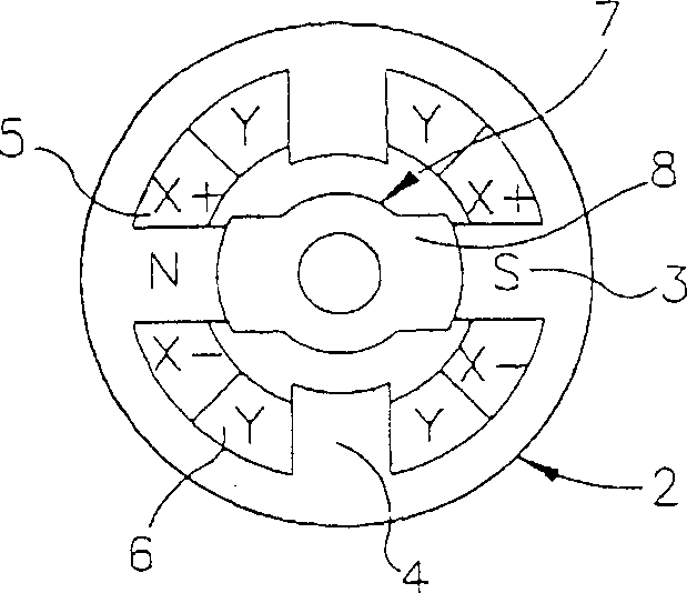
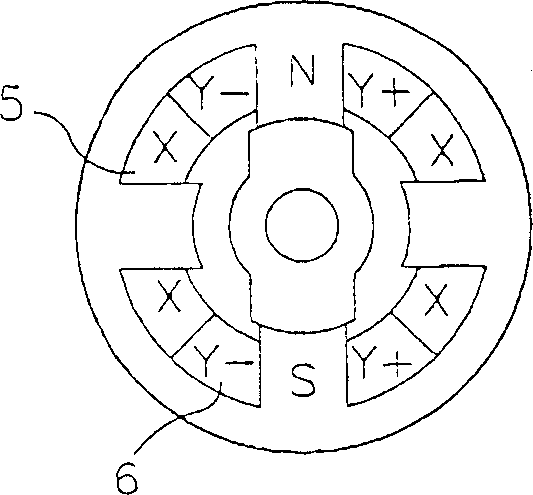
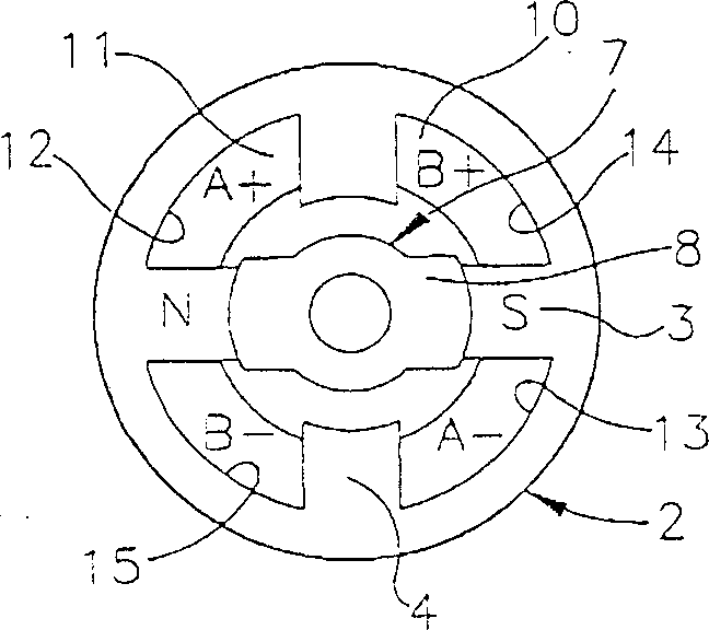
[0019] Embodiments of the invention will be described below with reference to a flux-switching motor having a four-pole stator and a two-pole rotor, wherein the stator has a field winding 10 and an armature winding 11 divided into two coils 24 and 25, these The coils are tightly coupled and wound such that diametrically opposed portions of the coils are located in diametrically opposed stator slots. For further explanation, the two armature coils are referred to as A 1 and A 2 .

[0020] In the circuit of FIG. 5, field winding 10 is connected in parallel with armature coils 24 and 25 and capacitor 57 so that the currents through field winding 10 and armature coils 24 and 25 are different. Powering the circuit from an AC source 58 by means of a rectifier bridge 59, the switch control circuit 60 alternately powers the armature coils 24 and 25 to provide magnetomotive forces acting in opposite directions for motor rotation. In this case, the circuit arrangement has two switche...


PUM


Abstract

An electrical machine or generator comprising a rotor (79) without windings, a stator (78) having several armature windings and several field windings and an electrical circuit arrangement, the armature winding comprising at least two active parts located in the stator The coils (A1, A2) in the armature winding slots (81) in the magnet, the active part of the field winding (F) are located in the field winding slots (80) in the stator magnet. The circuit device is used to control the current in the coils (A1, A2) synchronous with the rotation of the rotor, so that the period in which the current produces a magnetomotive force in one direction in one coil and the period in which the current produces a magnetomotive force in the opposite direction in the other coil alternate with each other. Armature winding slots and field winding slots are equal in number and alternate within the stator magnets. In addition, considering that the width of each slot (80, 81) is the maximum value in the direction of rotor rotation, the depth of each slot is the maximum value of the radial slot of the rotor, and the thickness of the back iron behind the slot is the maximum value of the slot along the same radial direction. The distance between the value and the maximum value of the armature magnet, the width of each armature winding slot (81) is greater than the width of each field winding slot (80), the thickness of the back iron behind each armature winding slot (81) Greater than the thickness of the back iron of each field winding slot (80). Such an arrangement optimizes power efficiency while making the best use of the magnetic material.

Description

technical field [0001] The present invention relates to electric machines. Background technique [0002] Figure 1a and 1b Represents a traditional two-phase variable reluctance motor, which includes a stator 2 with two pairs of salient poles 3, 4 facing inwardly, the salient poles are provided with two pairs of excitation windings 5, 6 corresponding to two phases, the The motor also includes a rotor 7 with a single pair of salient poles 8 facing outwards without winding. Each of the four excitation windings is wound on its corresponding magnetic pole, for example, the symbol Y-Y represents the two radially opposite parts of each winding in the winding pair 6, and the symbol X-X represents the two diameters of each winding in the winding pair 5. to the opposite part. A field circuit (not shown) is used to cause the rotor 7 to rotate within the stator 2 by alternately exciting the stator synchronously with the rotation of the rotor so as to take advantage of the tendency o...

Claims


Application Information

Patent Timeline
IPC IPC(8): H02K1/06H02K1/16H02K3/28H02K19/10
CPCH02K1/165H02K1/246H02K19/103
Inventor 李查德·T·瓦尔特
Owner BLACK & DECKER INC
Why Eureka
Try Eureka