
Planetary support structure in simple planetary gear mechanism and its manufacture

A technology of planetary gear and gear mechanism, which is applied in the direction of gear transmission, elements with teeth, belt/chain/gear, etc. It can solve the problems of inability to adopt planetary gear structure, internal tooth gear deformation, unfavorable durability, etc., and achieve The effect of smooth and smooth rotation effect

Inactive Publication Date: 2002-09-25
SUMITOMO HEAVY IND LTD
View PDF0 Cites 11 Cited by
  • Summary
  • Abstract
  • Description
  • Claims
  • Application Information

AI Technical Summary

Problems solved by technology

[0011] For example, the method of reducing the backlash with the structure proposed in No. 63-6248 mentioned above, although it is true that the tooth backlash can be reduced in the two directions of forward rotation and reverse rotation, but there will be such problems again, that is, Although equipped with 4 planetary gears, power transmission can only be realized through 2 gears during forward rotation and reverse rotation, and the amount of torque transmission is reduced by half
In addition, in order to maintain the same forward rotation torque and reverse rotation torque, the number of planetary gears corresponding to each should be consistent. In fact, it is limited to 4, and there is also a problem that the degree of freedom in design is small.
[0012] Related to this, it is well known that 3-point support is better than so-called 4-point support in terms of absorbing the dimensional error of each gear, or the position error (or allowable error) of assembly, but in this technology There will also be such a problem: in the structure where the backlash is adjusted as a pair of opposing pairs, it is impossible to adopt a structure including three planetary gears equivalent to 3-point support.
[0013] Similarly, the method of reducing backlash with the structure proposed in Patent Publication No. Hei 05-240315 also exists that only 2 of the 4 planetary gears are used to realize power transmission, therefore, a large transmission torque capacity cannot be maintained , and also cannot adopt a structure with 3-point supports
[0014] Also have, realize the method for reducing backlash with the proposed structure in the patent publication No. 08-61438, although all planetary gears all can forward and reverse the advantage that rotates, internally toothed gear must be made elastic body, this It will also bring problems such as poor processing performance and difficulty in maintaining strength.
In addition, the internal gear is deformed within the range of movement of the meshing position between the internal gear and each of the planetary gears, which is likely to cause disadvantages in terms of durability.

Method used


Image

  • Planetary support structure in simple planetary gear mechanism and its manufacture
  • Planetary support structure in simple planetary gear mechanism and its manufacture
  • Planetary support structure in simple planetary gear mechanism and its manufacture

Examples


Embodiment Construction

[0067] Hereinafter, examples of embodiments of the present invention will be described in detail based on the drawings.

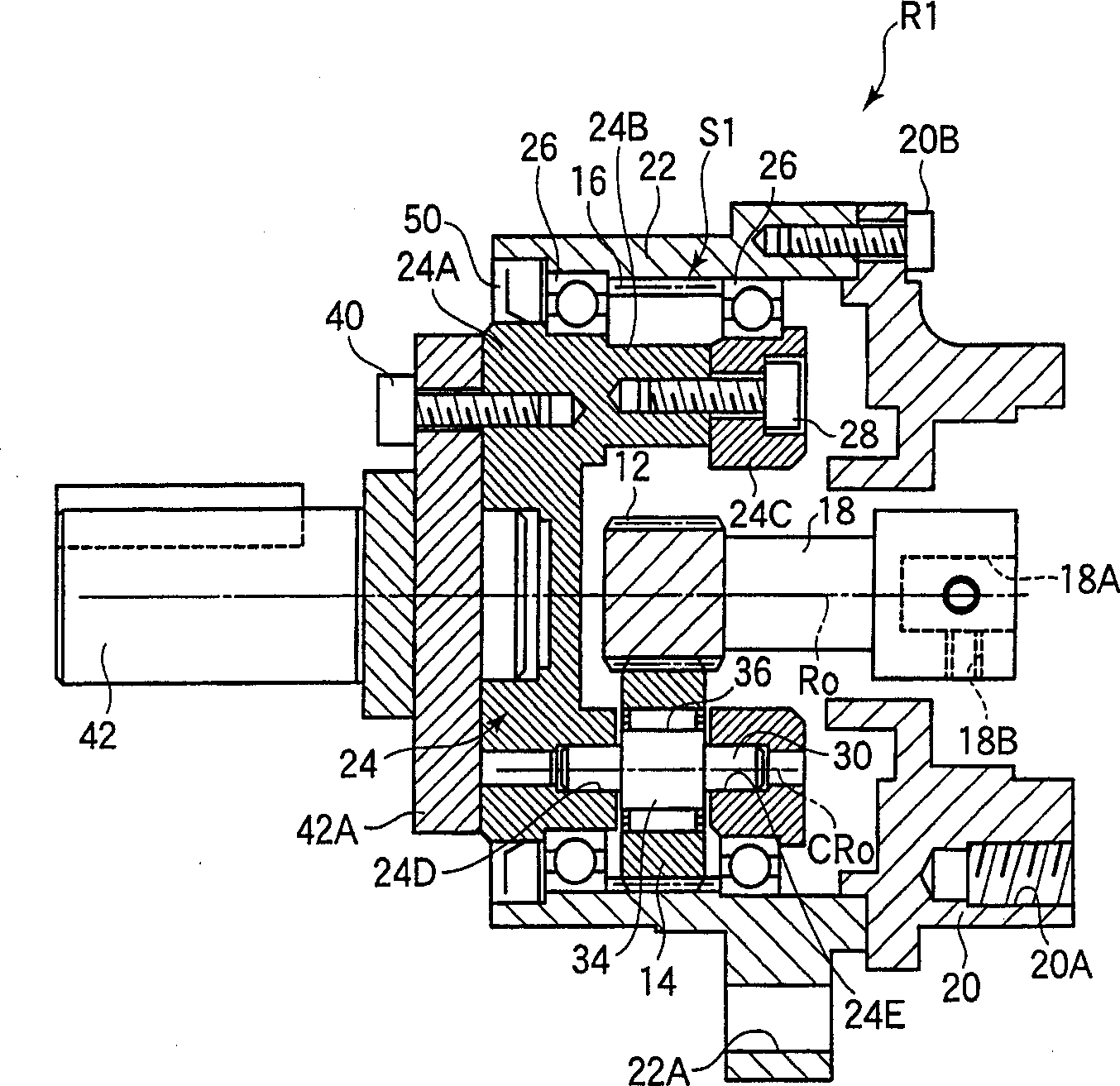
[0068] figure 1 It is a general longitudinal sectional view of a simple planetary gear reducer to which the present invention is applied.

[0069] The simple planetary gear mechanism S1 of this simple planetary gear reducer R1 is composed of a sun gear 12 , three planetary gears 14 circumscribing the sun gear 12 , and an internal gear 16 circumscribing the planetary gears 14 .

[0070] The above-mentioned sun gear 12 is directly cut on the input shaft 18 . The motor output shaft (omitted in the figure) is inserted into the groove 18A of the input shaft 18, and fixed on the threaded part 18B by tightening the bolt (omitted in the figure), so that the input shaft 18 and the motor output shaft are coupled together.

[0071] The motor is connected to the connecting cover 20 through the connecting bolt hole 20A, and the connecting cover 20 is connected to the ...


PUM


Abstract

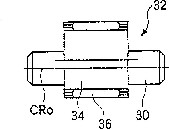
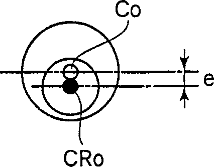
A simple planetary gear mechanism with an automatic centering function to support the planetary gears, thereby obtaining a reducer with reduced backlash through a simple method. The planetary gears (14) are supported by bracket pins (30) supported by the bracket. The bracket pin (30) includes a crank portion (32) which is eccentric "e" with respect to the axis of the bracket pin and whose eccentric angle α is variable. The planetary gear (14) is rotatably supported around the axis of the crank portion (32). As a result, by making the eccentric angle variable, the shaft centers of the planetary gears are automatically aligned in the radial direction when assembling each gear, so that the backlash can be adjusted to the minimum just by assembling a sun gear of an appropriate size.

Description

technical field [0001] The present invention relates to a support structure for planetary gears of a simple planetary gear mechanism. Background technique [0002] A simple planetary gear mechanism is composed of a sun gear, a planetary gear positioned on a support via a support shaft and circumscribed with the sun gear, and an internal gear inscribed with the planetary gear. This simple planetary gear mechanism can obtain a relatively high reduction ratio due to its compact structure, and it is easy to change the reduction ratio (or speed-up ratio) by changing the settings and the input and output of each component, etc., so it is widely used applied in a variety of different purposes. [0003] In the factory production line in recent years, because of the complexity of processing multiple items on the same production line at the same time, instead of using a single power to drive the entire production line as before, a dedicated motor with a reducer is installed in each d...

Claims


Application Information

Patent Timeline
IPC IPC(8): F16H1/28F16H55/18F16H57/08F16H57/12
CPCF16H1/2836F16H1/2863F16H1/28
Inventor 芳贺卓深谷末男畠中贵志
Owner SUMITOMO HEAVY IND LTD
Learn More