Control valve

A technology for controlling valves and valve bodies, applied in sliding valves, valve details, multi-way valves, etc., can solve the problems of increased volume of control valves, lack of freedom, and inability to determine the opening and closing patterns of valve ports separately

Inactive Publication Date: 2002-10-23
PACIFIC INDUSTRIAL CO LTD
View PDF0 Cites 9 Cited by
  • Summary
  • Abstract
  • Description
  • Claims
  • Application Information

AI Technical Summary

Problems solved by technology

Thus, if the number of valve ports increases, the radius of the imaginary circle where the valve ports should be set also increases, and as a result, the volume of the control valve increases
[0005] In addition, since the opening and closing of multiple valve ports provided on the same imaginary circle is controlled by one valve body, the opening and closing patterns of each valve port cannot be individually determined.
Therefore, the opening and closing control of the valve port lacks freedom

Method used


Image

  • Control valve
  • Control valve
  • Control valve

Examples


Embodiment Construction

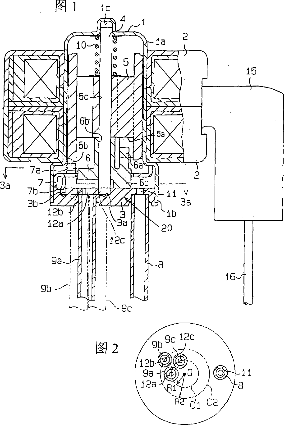
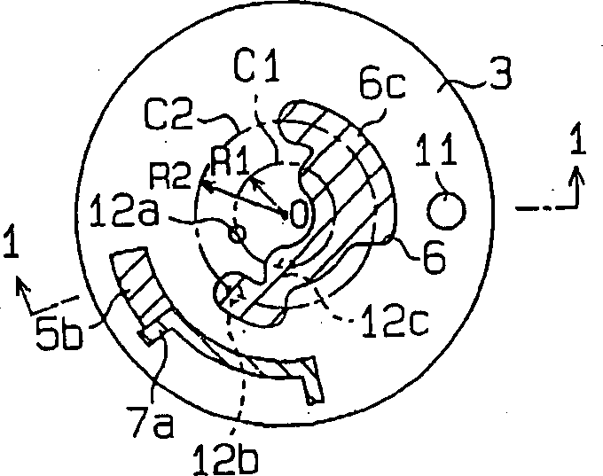
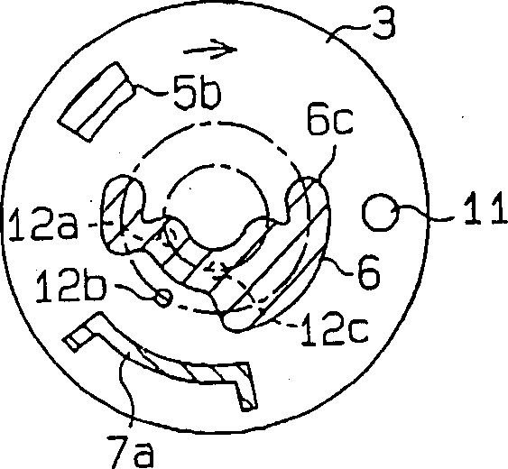
[0018] An embodiment of the present invention will be described in detail below with reference to FIGS. 1 to 4 . The control valve shown in Figure 1 is assembled, for example, in a cooling circuit (not shown in the figure) in a refrigerator, and the control valve is used to switch a plurality of refrigerant flow paths in the cooling circuit (for example, for refrigeration). circulation path and circulation path for refrigeration). The control valve includes a sealing shell 1 and a valve seat plate 3. The sealing shell 1 is cylindrical and has an opening at one end. The valve seat plate 3 is fixed to the opening end of the sealing shell 1 in a gas-tight manner. The above-mentioned sealed case 1 is formed of a non-magnetic metal. The sealed case 1 includes a smaller diameter portion 1 a, and a larger diameter portion 1 b provided near the open end of the sealed case 1 .

[0019] Around the smaller diameter portion 1a in the sealed case 1, a pair of electromagnetic coils 2 are ...


PUM


Abstract

A control valve, the control valve includes a valve seat plate, the valve seat plate has a plurality of valve ports; a valve body, the valve body faces the valve seat plate; a rotary drive mechanism, the rotary drive mechanism is used to make the valve body Rotate around a specified axis of rotation. In a state where the valve body is in contact with the valve seat, the valve body rotates in such a way that each valve port is opened and closed. The plurality of valve ports are provided on a plurality of imaginary circles having different radii centered on the rotation axis of the valve body. As a result, the number of valve ports can be increased without increasing the overall size of the control valve. In addition, a control valve having an excellent degree of freedom in opening and closing control of the valve port is obtained.

Description

technical field [0001] The present invention relates to a control valve for switching the flow path of fluid in a fluid circuit. Background technique [0002] For example, in a refrigerant circuit of a refrigerator, a control valve for switching the flow path of refrigerant in the refrigerant circuit is installed. As such a control valve, for example, a type has been proposed, which includes a valve seat and a valve body, the valve seat has a plurality of (for example, two) valve ports in a planar shape, the valve body and the valve body seat sliding contact. The valve body rotates around an axis perpendicular to the surface of the valve seat in a state of being in contact with the valve seat. Through the rotation of the valve body, the degree of opening of each valve port is adjusted. In addition, the rotation range of the above-mentioned valve body is limited to an angle range less than 360 degrees by the stopper. [0003] A refrigerant inflow pipe is connected to the ...

Claims


Application Information

Patent Timeline
Patent Type & Authority Applications(China)
IPC IPC(8): F16K3/06F16K11/074F16K31/04F25B41/04
Inventor 豊田和政
Owner PACIFIC INDUSTRIAL CO LTD
Why Eureka
Try Eureka