Optical diagnostic instrument for observing eye

A diagnostic instrument and eye technology, applied in the field of optical diagnostic instruments, can solve the problems of poor accuracy, low diagnostic efficiency, poor flexibility, etc., and achieve the effect of reducing misdiagnosis, high diagnostic efficiency and high accuracy

Inactive Publication Date: 2002-10-30
SHANGHAI INST OF OPTICS & FINE MECHANICS CHINESE ACAD OF SCI
View PDF2 Cites 8 Cited by
  • Summary
  • Abstract
  • Description
  • Claims
  • Application Information

AI Technical Summary

Problems solved by technology

[0004] 1. Single function
like figure 1 The system shown can only observe the subject's eye 1 by the observer, but cannot record the digital image of the iris of the subject's eye 1; figure 2 The device shown can only obtain a digital image of the iris of the subject's eye 1, and the observer cannot directly see the texture structure of the iris
[0005] 2. Low diagnostic efficiency and poor accuracy
because for figure 1 The device shown can only be diagnosed and analyzed by the observer on the texture structure of the iris of the subject's eye 1, the diagnostic efficiency is low, there is a certain degree of subjectivity, and t...

Method used


Image

  • Optical diagnostic instrument for observing eye
  • Optical diagnostic instrument for observing eye
  • Optical diagnostic instrument for observing eye

Examples


Embodiment Construction

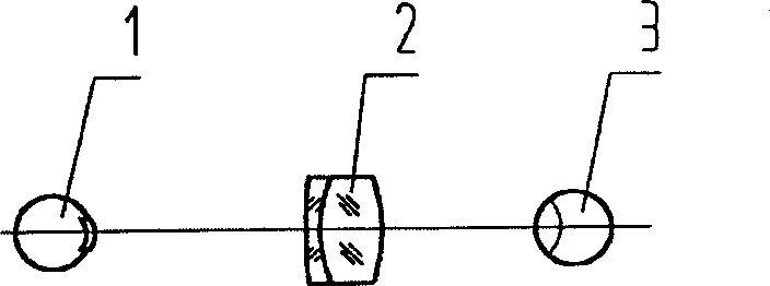
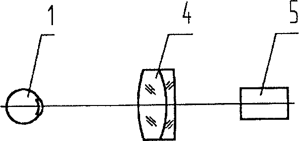
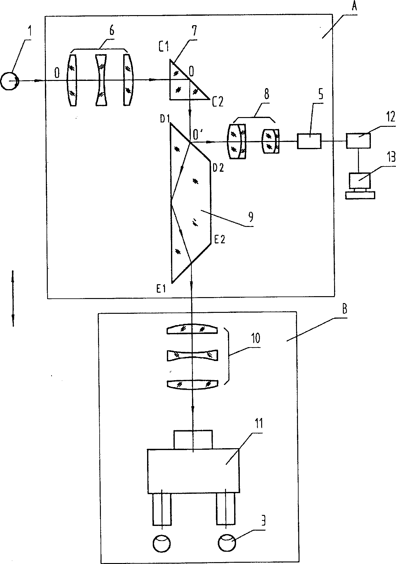
[0024] Such as image 3 shown in the structure. The collimating mirror 6 adopts a three-piece separation mirror group, and its focal length is 150mm; the distance between the subject's eye 1 and the first optical surface of the collimating mirror 6 is 127mm, so it can be seen that the working distance is large, and it will not be harmful to the subject. The examiner’s eyes are damaged; the reflective element 7 adopts a right-angle prism, and its light aperture is 25mm×25mm; the light aperture of the Dove prism 9 is 25mm×25mm, and its incident surface D 1 D. 2 It is coated with a broadband dielectric spectroscopic film, which has uniform reflectivity and transmittance in the 400nm-700nm band, with a reflectivity of 20% and a transmittance of 80%, so as to ensure that the image colors of the two optical paths are realistic and consistent; observe The structure of focusing mirror 10 is identical with collimating mirror 6, but wherein the direction of each optical lens is opposi...


PUM


Abstract

An optical diagnosing instrument for observing human eye iris and obtaining the image and data of iris at same time is composed of the optical camera-computer channel and the optical channel for visual observation, which device the light axises perpendicular to each other. Said optical channel for camera and computer consists of collimator, reflector, incident surface of prism, focusing lens and camera connected to computer via A/D converter. Said optical channel for visual observation has focusing lens for observation and binocular eyepiece. Its advantages are more functions, high diagnosingefficiency and high correctness.

Description

Technical field: [0001] The invention relates to an optical diagnostic instrument for observing the eyes, which is mainly used for observing the iris of the human eye and obtaining iris images and data at the same time. The images can be observed and preserved for disease diagnosis or identification. Background technique: [0002] In the prior art, the inventor Luo Yonghong provided an optical device of an "iris inspection aid" in a utility model patent (patent No. ZL92235084.1), the structure of which is as follows: figure 1 shown. The optical device of the utility model patent (patent number ZL99217063.X) "iris image acquisition device" provided by the Institute of Automation, Chinese Academy of Sciences, the structure is as follows figure 2 shown. prior art[1] figure 1 The observer's eye 3 observes the subject's eye 1 through a magnifying glass 2, which is usually a short-focus monocular eyepiece. prior art[2] figure 2 , using a camera lens 4 to image the subject's...

Claims


Application Information

Patent Timeline
IPC IPC(8): A61B3/12A61B6/00
Inventor 黄惠杰赵永凯杜龙龙程兆谷路敦武
Owner SHANGHAI INST OF OPTICS & FINE MECHANICS CHINESE ACAD OF SCI
Why Eureka
Try Eureka