Interface device with different transmission mode between two remote systems
A technology of a remote control system and an interface device, applied in the field of interface devices, can solve the problems of complicated connection relationship and the like
- Summary
- Abstract
- Description
- Claims
- Application Information
AI Technical Summary
Problems solved by technology
Method used
Image

Examples
no. 2 example
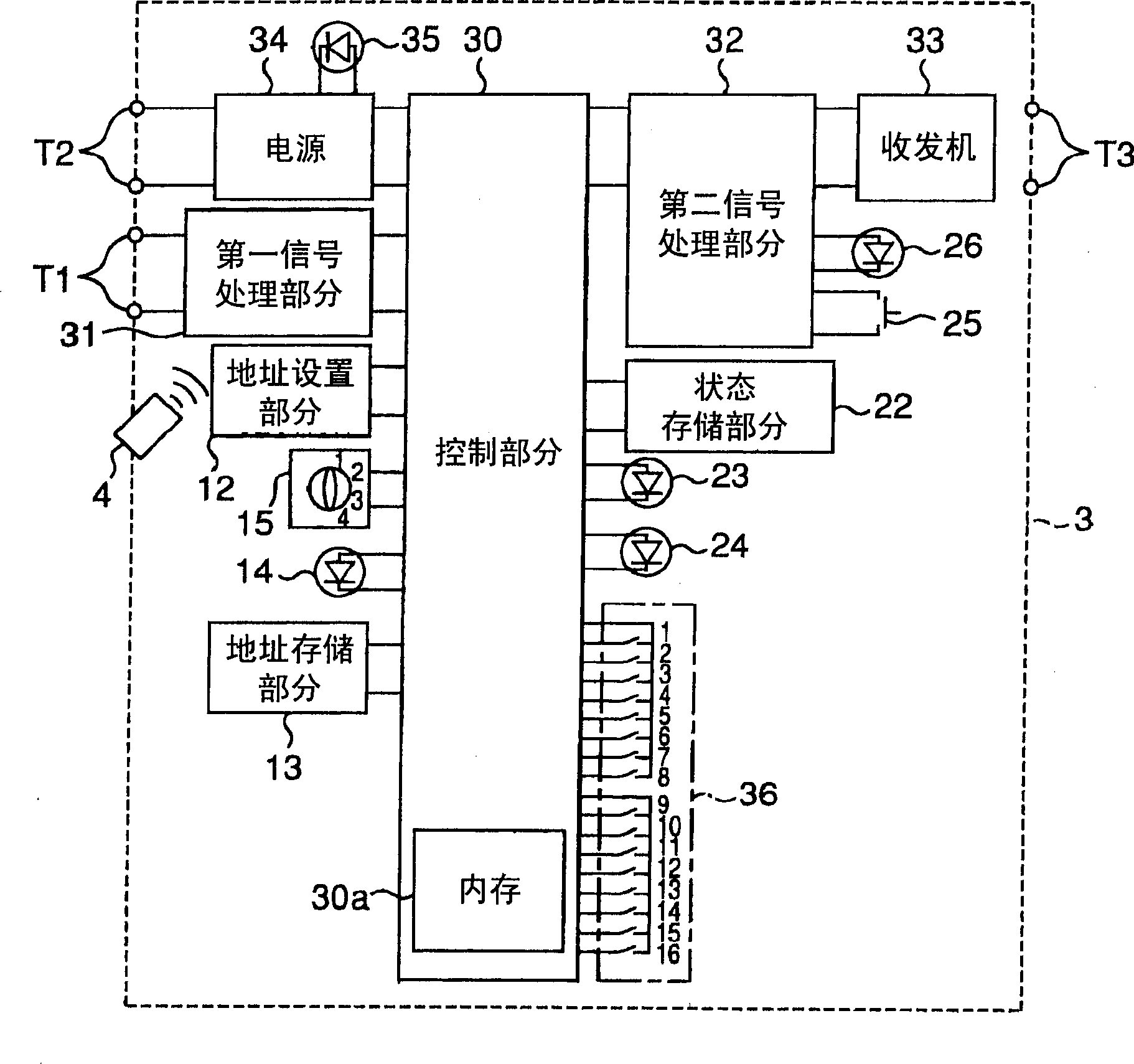
[0077] Figure 7 It is a structural block diagram of the inter-system interface device 3 of the second embodiment of the present invention, which omits the "operation" function ("operation" from the contention communication system 2 to the polling communication system 1) in the first embodiment formed later.
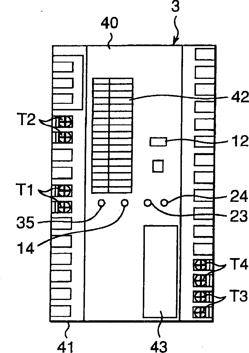
[0078] Figure 8 is being Figure 7 The front view of the part covered by the door 43 in the second embodiment shown, in the second embodiment, there is no direction selection switch 36, and only the combination switch 15 is installed in the door 43 on the front of the equipment box 40 , work plug 25 and work light 26, such as Figure 8 shown.
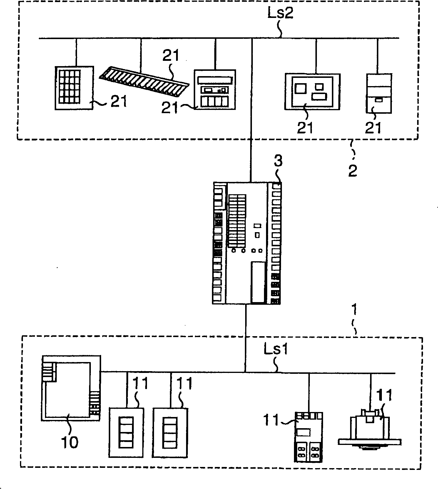
[0079] Figure 9 It is an interface device 3 installed between the polling communication system 1 and the contention communication system 2 (such as Figure 7 As shown in the control content explanatory diagram of ), because only the "operation" from the polling communication system 1 to the contention communication system ...
no. 3 example
[0082] Figure 10 It is an explanatory diagram of the control content of the inter-system interface device 3 installed between the polling communication system 1 and the contention communication system 2 according to the third embodiment of the present invention.
[0083] Contrary to the second embodiment, the structure of the third embodiment is formed by canceling the "control" function from the polling communication system 1 to the contention communication system 2 in the first embodiment, therefore, in this embodiment and no need to provide figure 1 The direction selector switch 36 in , because only the "control" from the contending communication system 2 to the polling communication system 1 is performed. Figure 5 The function of "switch" in this case, (such as Figure 10 shown) disappeared. Other structures and working elements are the same as the first embodiment.
[0084] Because this structure is specially used to "control" from the polling communication system 1...
no. 4 example
[0086] see Figure 9 , in order to command the "operation" from polling communication system 1 to contention communication system 2, a "single" address of polling communication system is taken, in other words, a switch operation of polling communication system 1 and contention communication system 2, but the polling communication system 1 has the function of controlling a group of loads ("group" control and "mode" control) with a switch, so if the same function is to be used in the nodes of the contention communication system 2 It is also very convenient to realize in the unit 21, that is to say, because the number of valid addresses in the polling communication system 1 is limited, the one-to-one correspondence or mapping between the terminal unit 11 and the node unit 21 can reduce the number of addresses used for polling communication. The number of effective addresses of the terminal units 11 in the system 1 is therefore a structure that allows the addresses of the node uni...
PUM
 Abstract
Description
Claims
Application Information
 - R&D
- Intellectual Property
- Life Sciences
- Materials
- Tech Scout
- Unparalleled Data Quality
- Higher Quality Content
- 60% Fewer Hallucinations
Browse by: Latest US Patents, China's latest patents, Technical Efficacy Thesaurus, Application Domain, Technology Topic, Popular Technical Reports.
© 2025 PatSnap. All rights reserved.Legal|Privacy policy|Modern Slavery Act Transparency Statement|Sitemap|About US| Contact US: help@patsnap.com