
Car cowl structure of motor bicycle

A technology for motorized two-wheeled vehicles and car covers, applied in the direction of machines/engines, vehicle parts, mechanical equipment, etc., can solve the problems of importing and inability to effectively cool the exhaust pipe, and achieve the effect of small car covers

Inactive Publication Date: 2002-11-13
HONDA MOTOR CO LTD
View PDF1 Cites 1 Cited by
  • Summary
  • Abstract
  • Description
  • Claims
  • Application Information

AI Technical Summary

Problems solved by technology

[0004] But above-mentioned two-wheeled motor vehicle with car cover, when the running air inlet 71 is enlarged, it is often easy to see the part surrounded by the lower cover 47.
[0005] In addition, when the running wind inlet 71 cannot be made large enough, the prescribed running wind cannot be introduced into the exhaust pipe 32 and the expansion chamber 33, and the exhaust pipe 32 and the expansion chamber 33 cannot be effectively cooled.

Method used


Image

  • Car cowl structure of motor bicycle
  • Car cowl structure of motor bicycle
  • Car cowl structure of motor bicycle

Examples


Embodiment Construction

[0019] Embodiments of the present invention will be described below with reference to the accompanying drawings. "Front", "Rear", "Left", "Right", "Up" and "Down" refer to the direction seen from the driver, and the drawing surface is the drawing seen from the direction indicated by the symbol.

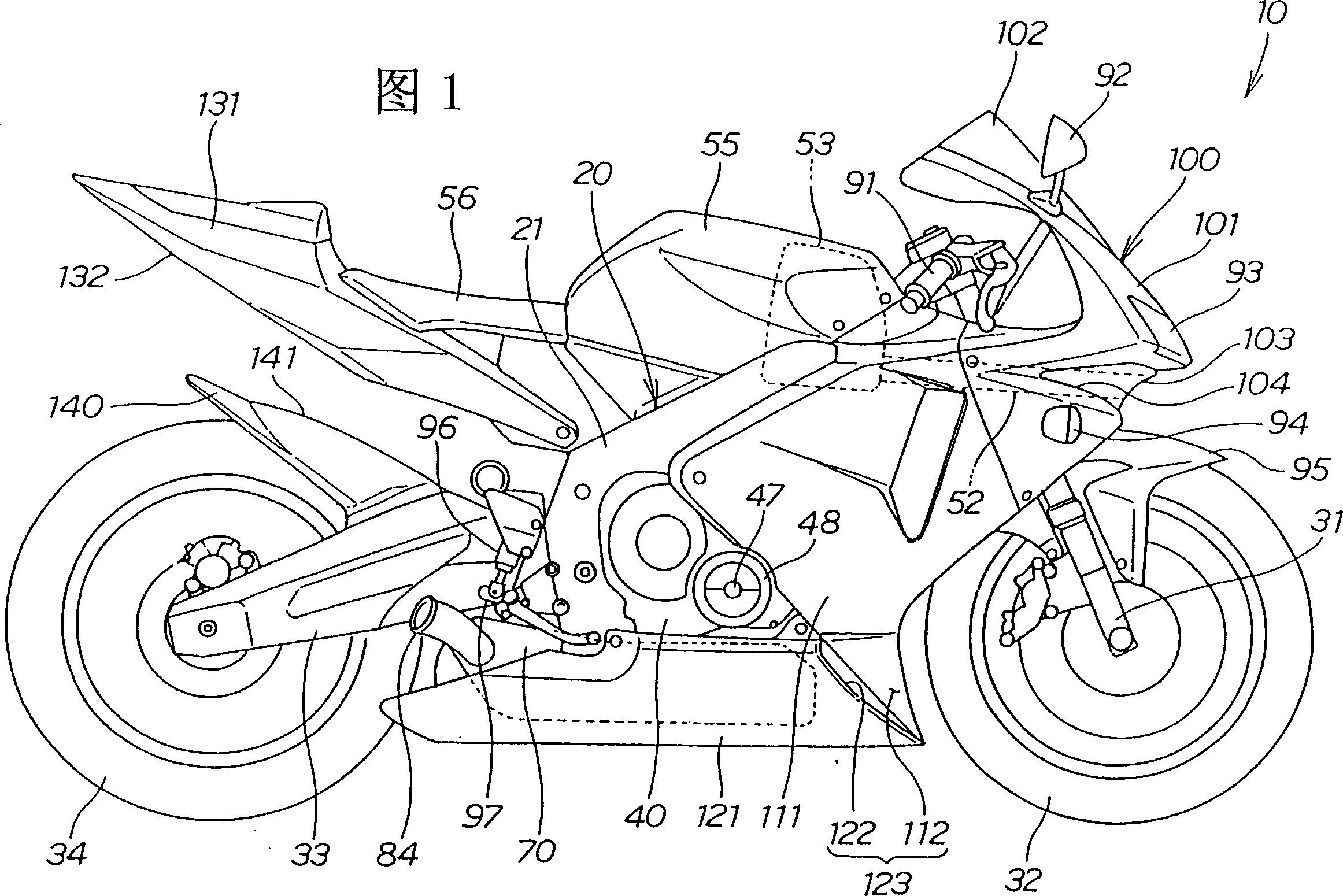
[0020] Fig. 1 is a side view of a motorcycle employing the vehicle cover structure of the present invention, showing the appearance of the motorcycle.

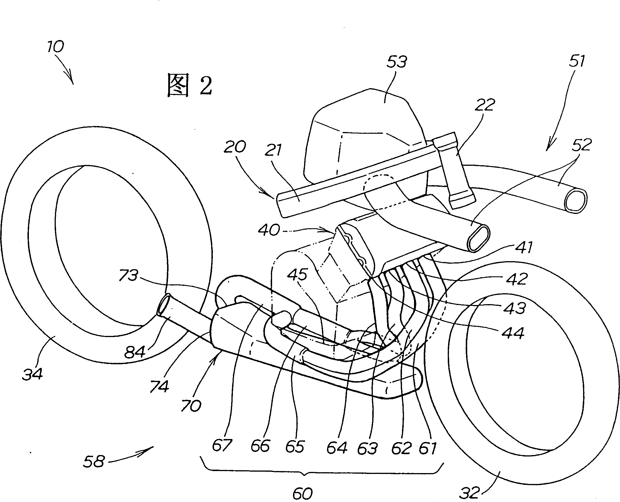
[0021] The motorcycle 10 has a front wheel 32 mounted on the front of the frame 20 via a front fork 31, a rear wheel 34 mounted on the rear of the frame 20 via a swing arm 33, and a rear wheel 34 mounted on the center of the frame 20 in the longitudinal direction. The lower engine 40 , the air cleaner 53 , the fuel tank 55 , and the vehicle seat 56 are mounted on the center upper portion in the longitudinal direction of the vehicle frame 20 .

[0022] The present invention is characterized in that an inline four-cylinder engine 40 is...


PUM


Abstract

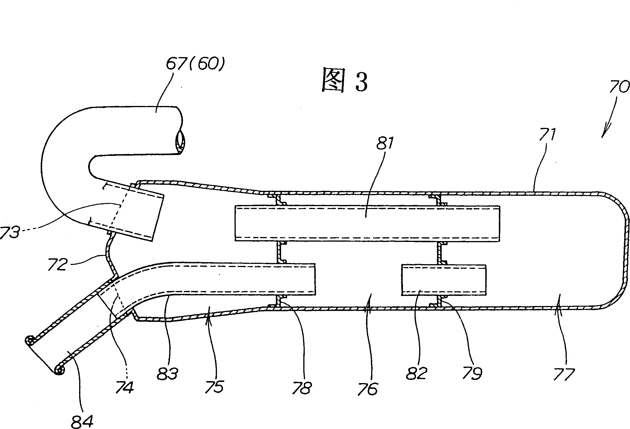
The vehicle cover 100 is detachable at the position in front of the muffler 70, a recessed portion is formed at the rear end of the middle cover 111 (front side cover) toward the center of the vehicle body, and a front opening 122 is formed at the front end of the lower cover (rear side cover). , the front opening 122 and the recess together form a large air guide port 123 for cooling the muffler 70 . For example, the front cover can be covered with the rear cover, so that the interior can not be easily seen. As a result, a large air guide port for cooling the muffler can be formed, and the muffler can be sufficiently cooled.

Description

technical field [0001] The present invention relates to a vehicle cover structure of a motorcycle. Background technique [0002] As a cover structure for a motorcycle, for example, "a motorcycle with a cover" disclosed in Japanese Utility Model Publication No. 2-10071 is known. [0003] The above-mentioned technology, according to Fig. 2 and Fig. 3 of the same publication, in the above-mentioned motorcycle with a car cover, the running wind inlet 71 and the guide part 72 for introducing the running wind are integrally arranged on the lower side of the lower cover 47. 49, the exhaust pipe 32 and the expansion chamber 33 are actively cooled by introducing the traveling wind from the traveling wind inlet 71. [0004] But above-mentioned two-wheeled motor vehicle with car cover, when the running air inlet 71 is enlarged, it is often easy to see the part surrounded by the lower cover 47. [0005] In addition, if the traveling wind inlet 71 cannot be made sufficiently large, pre...

Claims


Application Information

Patent Timeline
IPC IPC(8): B62J17/00B60K13/04B62J23/00F01N13/08
Inventor 津久井浩明三上孝雄
Owner HONDA MOTOR CO LTD
Learn More