

Turbine propeller and turbine engine
A technology for turbines, turbine blades, applied in the direction of supporting elements of blades, mechanical equipment, engine elements, etc.
- Summary
- Abstract
- Description
- Claims
- Application Information
AI Technical Summary
Problems solved by technology
Method used
Image

Examples
Embodiment Construction
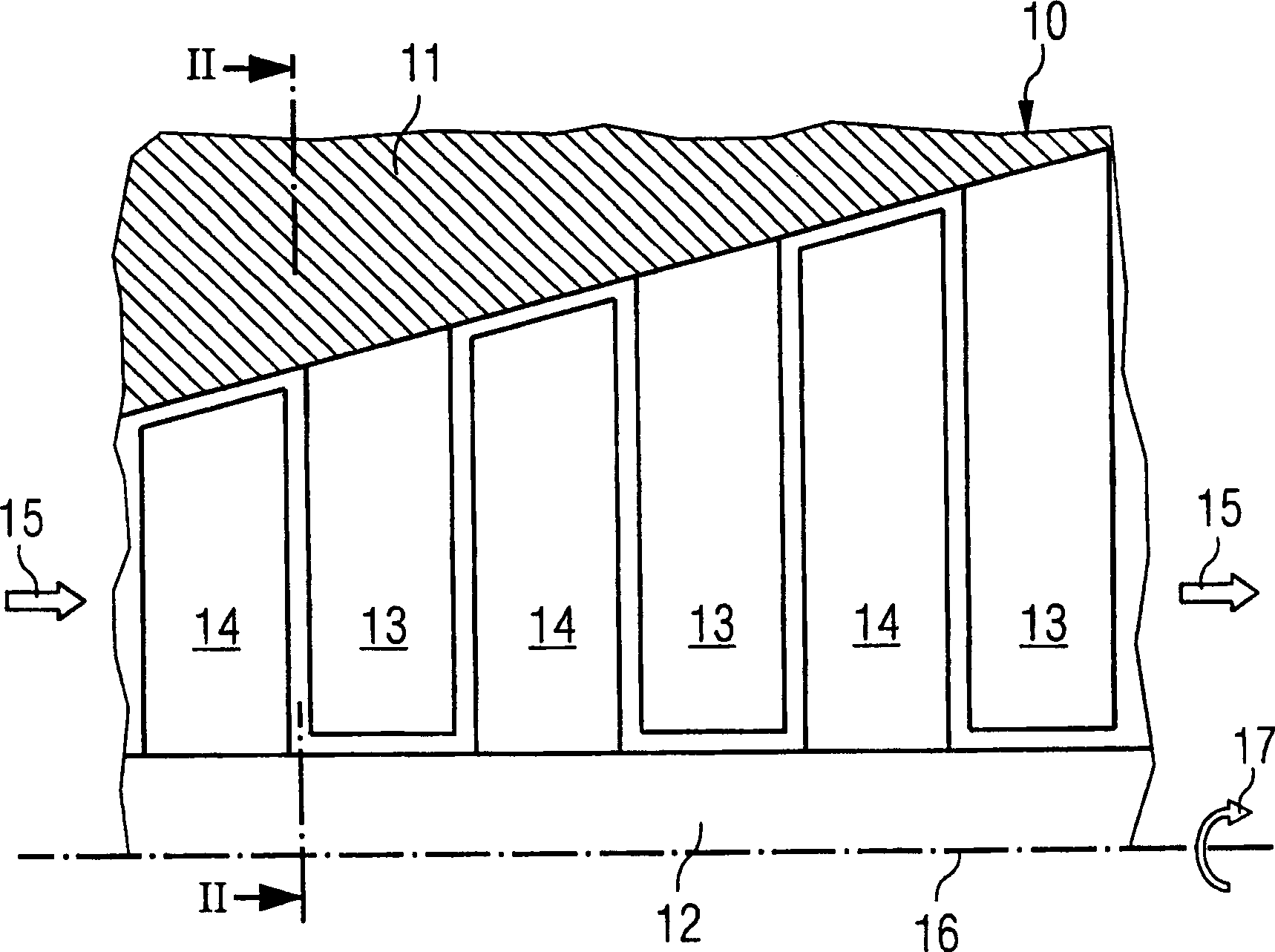
[0024] figure 1 A schematic longitudinal section of a gas turbine 10 with a housing 11 and a rotor 12 is shown. The casing 11 has stationary blades 13 and the rotor 12 has moving blades 14 . The hot flue gases pass through the gas turbine 10 in the direction of arrow 15 , causing the rotor 12 to rotate about an axis of rotation 16 in the direction of arrow 17 .
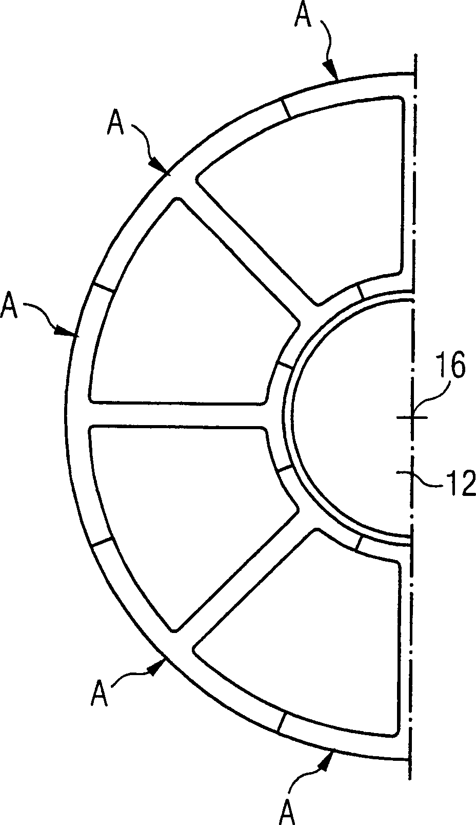
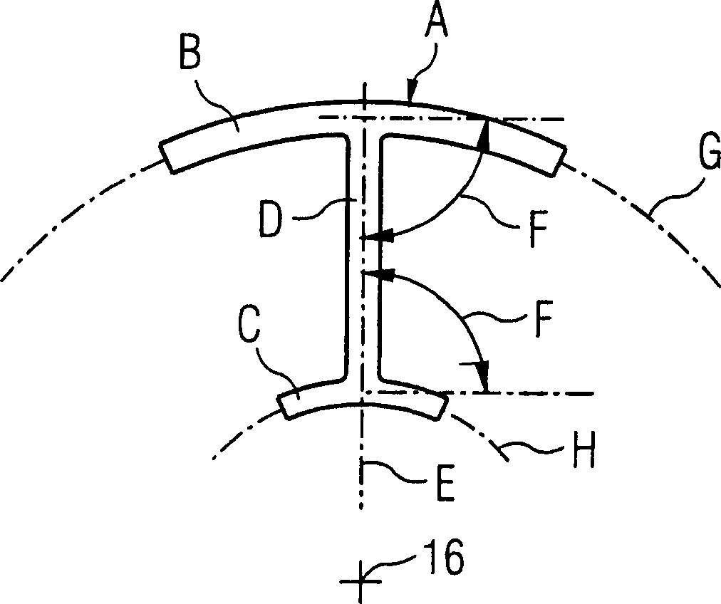
[0025] Figures 2 to 4 A design according to the prior art is shown. especially in figure 2 and image 3 As shown in , a plurality of stator blades A are arranged uniformly on the circumference of the gas turbine 10 . Each stationary blade A has a bottom plate B for fixing on the casing 11 and covering the gap between the two stationary blades A, a top plate C and a blade airfoil D between them. The longitudinal axis E of the blade profile passes through the axis of rotation 16 of the rotor 12 . Each base and top plate B, C protrudes from the blade airfoil D at a right angle F. For convenience of description,...
PUM
 Abstract
Description
Claims
Application Information