Network switch for failure restoration

A network, failure technology, applied in the field of automatic protection conversion system, can solve problems such as impact

Inactive Publication Date: 2002-11-13
THE TRUSTEES OF COLUMBIA UNIV IN THE CITY OF NEW YORK
View PDF1 Cites 7 Cited by
  • Summary
  • Abstract
  • Description
  • Claims
  • Application Information

AI Technical Summary

Problems solved by technology

Whereas failures in telephone networks once meant phone callers had to hang up and try again later, failures today can be devastating

Method used


Image

  • Network switch for failure restoration
  • Network switch for failure restoration
  • Network switch for failure restoration

Examples


Embodiment Construction

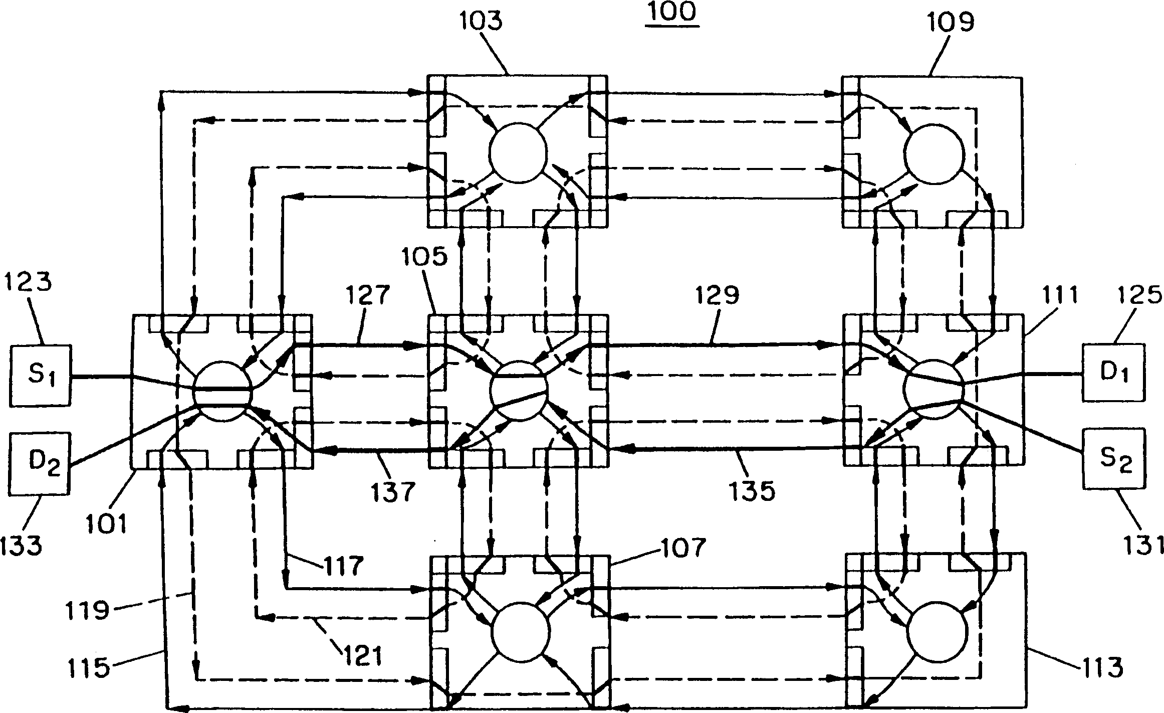
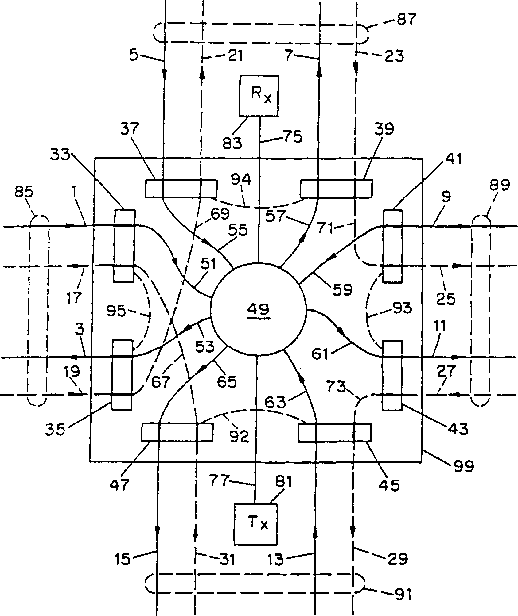
[0036] Automatic protection switching ("APS") for node failures requires rapid recovery from any failure of network nodes. A network node is any site that contains switching equipment (including protection switches) and is connected to one or more links and possibly end-user equipment. Its purpose is to communicate between successive links and the end-users of each intermediate node. Create a data link. The link can be composed of one or more data pipes for transmitting data (including any form of information). In the preferred embodiment, the optical fiber will be described as a pipe, so that a link will consist of a pair of optical fibers carrying traffic in opposite directions. The central switch in the node is preferably an optical switch in this embodiment.

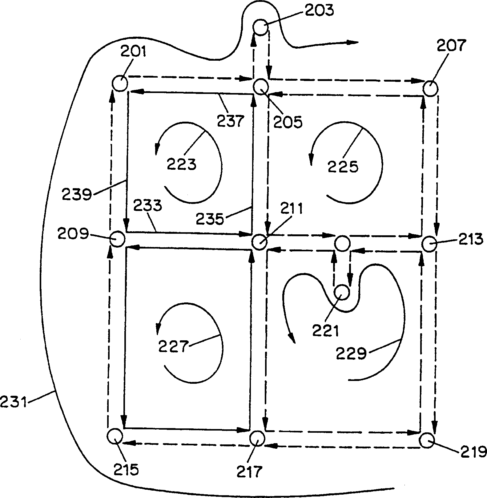
[0037] The network contains two or more nodes selectively connected by links in a specific configuration. In this preferred embodiment, each link in the network contains many optical fibers, and each optical fiber carrie...


PUM


Abstract

A system and method for automatically restoring a network containing failed converter nodes. A protection ring is generated for network restoration, and a ring group is generated from the protection ring. Each node is equipped with a protection switch (105) internally interconnecting the input / output to the connection link through the interconnecting protection fiber. The selection of which inner protection fiber to switch traffic on allows configuration of nodes to create merged ring groups. In this way, if a failure of the central converter is detected, the transmission information is diverted to the selected protection fiber of the corresponding merged ring group, so that the information can automatically pass through the protection fiber bypassing the faulty node. Each protection switch has associated with it mapping data that defines which protection fiber should be switched to in terms of input and output links for transmissions that need to be sent through the node. The system and method are applicable to both non-planar and planar networks.

Description

[0001] Related application [0002] This application relates to the US application number 09 / 331,437 named "Automatic Protection Switching System in a Network" ("Automatic Protection Switching System in a Network") filed by Ellinas and Stern, and requires priority to the PCT application number PCT / US96 / 20598 Right, both applications are hereby incorporated by reference. Technical field [0003] The invention relates to an automatic protection switching system and method for recovering switching failures in a network. Background technique [0004] Today's communication systems used to send data from source to target are usually high-speed, high-capacity systems that handle many different types of user services. An example of such a system is an optical fiber network used for telephone traffic or other data exchange. These advanced networks can transmit large amounts of information at a given time. Such a network usually consists of links connected to nodes on the network that conve...

Claims


Application Information

Patent Timeline
Patent Type & Authority Applications(China)
IPC IPC(8): H04B10/02H04B1/74H04B10/00H04B10/08H04B10/12H04B10/20H04B17/00H04L12/26H04M3/00H04M3/22H04Q3/52
CPCH04J14/0227H04J14/0241H04J14/0284H04J14/0291H04Q11/0062H04Q2011/0081H04Q2011/009H04Q2011/0092
Inventor G·埃林纳斯T·E·斯特恩
Owner THE TRUSTEES OF COLUMBIA UNIV IN THE CITY OF NEW YORK
Why Eureka
Try Eureka