
Apparatus and method for indicating target by image processing without three-dimensional modeling

A target and image technology, applied in the field of image recognition, can solve problems such as assembly trouble

Inactive Publication Date: 2002-11-20
KONINKLIJKE PHILIPS ELECTRONICS NV
View PDF5 Cites 20 Cited by
  • Summary
  • Abstract
  • Description
  • Claims
  • Application Information

AI Technical Summary

Problems solved by technology

This is cumbersome to assemble as it requires multiple cameras and often quite complex 3D reasoning and computational intensifiers

Method used


Image

  • Apparatus and method for indicating target by image processing without three-dimensional modeling
  • Apparatus and method for indicating target by image processing without three-dimensional modeling
  • Apparatus and method for indicating target by image processing without three-dimensional modeling

Examples


Embodiment Construction

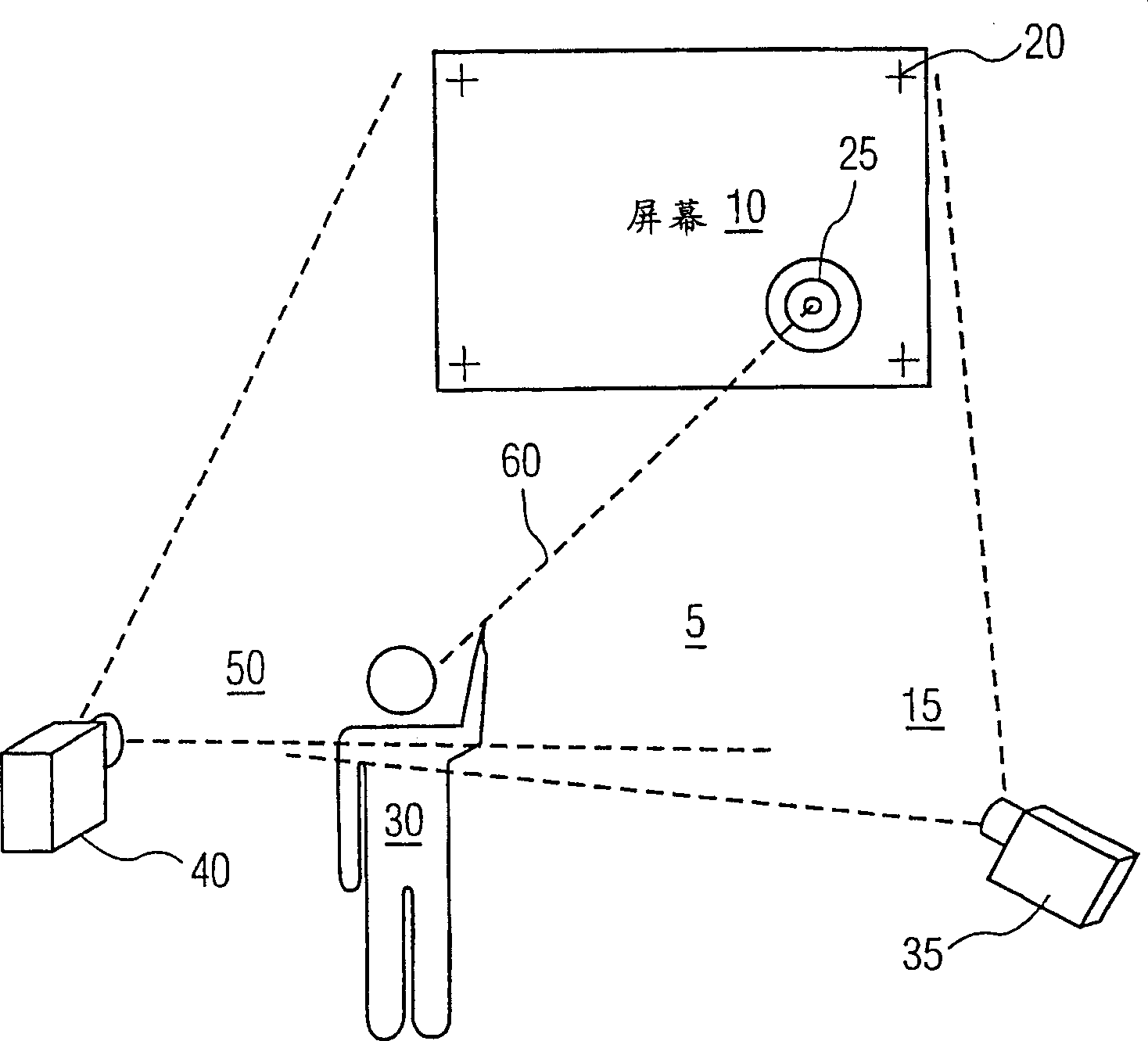
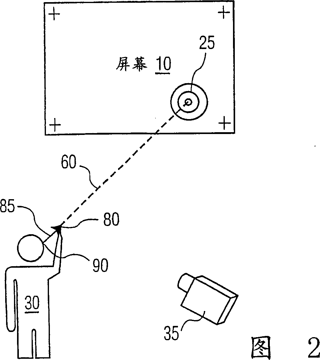
[0036] refer to figure 1 , the user 30 indicates an object 25 located in / on a plane like a television or projection screen 10 or a wall (not shown). Combining the images from the two cameras 35 and 40 in the manner described below enables identification of the target location in either of the two cameras 35 and 40 . The illustration shows user 30 pointing at target 25 with a pointing gesture. It has been experimentally determined that the user's gesture for pointing at the target is: the user's fingertip, the user's right (left) eye and the target are in a straight line. This means that the planar projection of objects in the field of view of either camera follows the rectilinear planar projection defined by the user's eyes and fingertips. In the present invention, the two plane projections are transformed into common plane projections, which can be any one of the cameras 35 and 40 or any third plane.

[0037] Referring to FIG. 2 , the cameras are aimed so that they each ca...


PUM


Abstract

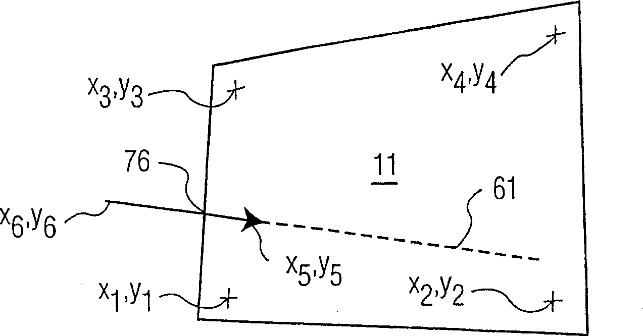
Using a pair of cameras, the coordinates of a target on a plane to which a user is pointing may be obtained without three-dimensional modeling and using only data derived from the respective images and no three-dimensional scene data. Each camera views at least four registration points on the plane and an indicator of a direction along which the target lies. A linear transform of a first image maps the planar projection of the direction indication into the second image. The coordinates, in the second image, of the target are determined from the intersection of the projection of the direction in the second image and the transformed projection from the first image. In another embodiment, the directions are mapped to a third reference frame or image by respective linear transforms. An application of the system would allow a user to indicate a location on a projection or television screen using a static pointing gesture. No information about the locations of the cameras is required, so the system can be set up quickly.

Description

[0001] Related Application Cross Reference [0002] This application is related to the following applications, which are hereby incorporated by reference in their entirety: [0003] US Application 09 / 488,028 for "Multi-Model Video Object Acquisition and Redirection System and Method," filed 1 / 20 / 2000 [0004] US applications 09 / 532,820 and [0005] US Application 08 / 995,823 for "Method and System for Selectable Option-Based Gestures" filed 12 / 22 / 2000 technical field [0006] The present invention relates to image recognition, in particular the recognition of pointing gestures for pointing target points on a plane without three-dimensional modeling of the scene. Background technique [0007] There are many applications that can benefit from gesture recognition. For example, this is a natural mechanism for controlling the aiming of cameras. Another application is using gestures to move an on-screen cursor. For example, it is conceivable to make selections on future smart ...

Claims


Application Information

Patent Timeline
IPC IPC(8): G06F3/033G06T1/00G06F3/00G06F3/01G06F3/0346G06F3/042G06T7/60
CPCA63F2300/1093G06F3/017G06F3/0304G06F3/0325
Inventor D·魏恩沙尔M·S·李
Owner KONINKLIJKE PHILIPS ELECTRONICS NV
Learn More