
Video data transmission/reception system in which compressed image data is transmitted from a transmission-side apparatus to a reception-side apparatus

a video data and reception system technology, applied in the field of video data transmission/reception system, can solve the problems of increasing the processing load of the user terminal, heavy load on the user terminal, and the period of time in which video is not displayed, so as to achieve the effect of increasing the processing load

Inactive Publication Date: 2010-06-22
PANASONIC CORP
View PDF16 Cites 30 Cited by
  • Summary
  • Abstract
  • Description
  • Claims
  • Application Information

AI Technical Summary

Benefits of technology

[0015]In view of the stated problem, the object of the present invention is to provide a video data transmission / reception system in which when video data, which has been encoded using motion compensation, must be decoded from part way through a GOP for the above-described reason, a reception-side user terminal is able to correctly decode and display the part of broadcast video data that occurs directly after transmission resumption (part way through the GOP), without greatly increasing the processing load on either the transmission side or the reception side.
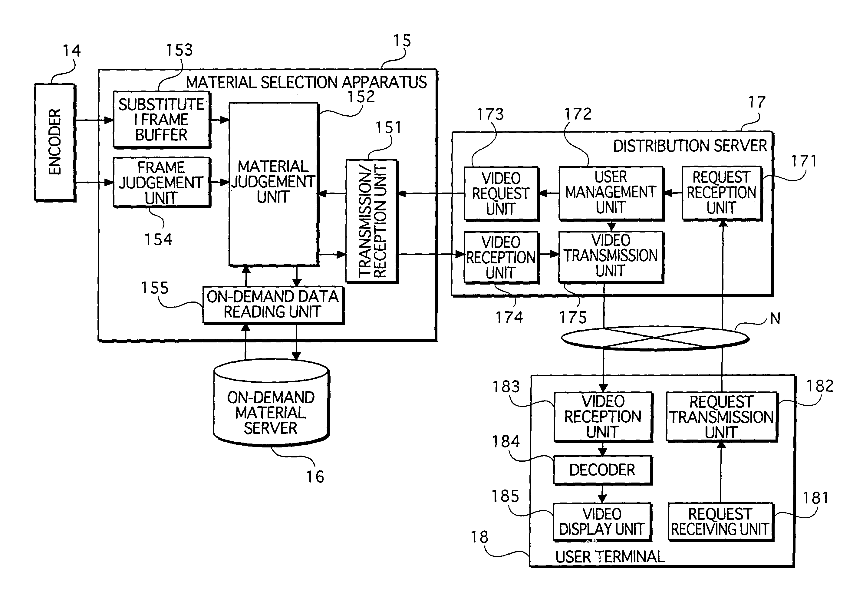
[0017]In this video data transmission / reception system, when resuming transmission of video data to the reception terminal that has temporarily stopped reception, if the frame data directly after resumption is an interframe encoded frame (a P frame or a B frame), substitute I frame data that has been generated separately by intraframe encoding the same frame is transmitted to the user terminal-side. The user terminal first decodes the substitute I frame data, and then decodes subsequent frame data using the decoded substitute I frame data as reference frame data. Accordingly, decryption can be performed correctly directly after resumption (part way through a GOP), and therefore video data display is not interrupted. Furthermore, there is no increase in the processing load of the user terminal, and the only increase in the processing load of the transmission-side apparatus is that for generating substitute I frame data and storing several frames' worth of the substitute I frame data. Even in a system in which video data is frequently stopped and resumed, the number of users to whom simultaneous broadcasting can be performed is not limited due to a processing load for stopping and resumption.
[0023]Furthermore, a structure is possible in which the transmission unit includes a broadcast transmission sub-unit operable to broadcast a same data to a plurality of transmission destinations; and an individual transmission sub-unit operable to transmit individual data to an individual transmission destination, and uses the broadcast transmission sub-unit to transmit the video data, and the individual transmission sub-unit to transmit the substitute I frame data, and the option data transmission unit transmits the option video data in an individual transmission manner. In this case, since the same video data is broadcast, there is no increase in the processing load of the transmission-side apparatus even if the number of reception terminals increases. In addition, if the transmission unit includes a switch sub-unit operable to exempt a reception terminal to which substitute I frame data or option video data is being transmitted from being a target of transmission of the video data by the broadcast transmission sub-unit, the reception terminal does not receive the broadcast video data simultaneously with the option video data or the substitute I frame data. Therefore, large increases in the load of the network and the processing load of the reception terminal can be avoided. Moreover, a possible structure is one in which the option data transmission unit includes an insertion sub-unit operable to transmit secondary option data part way through transmission of the option data; and a third encoding sub-unit operable, after transmission of the secondary option data ends and before transmission of the option data resumes, to generate option data substitute I frame data that corresponds to at least one frame of the option data starting from a frame that is a first frame after transmission resumption, wherein when transmission of the option data is to resume after the transmission of the secondary option data ends, the option data transmission unit transmits the option data substitute I frame data to the reception terminal before transmission of the option data resumes. If this structure is used, instead of option data being inserted in video data, option video data can be inserted in other option video data, and the stated effect can be achieved, i.e. the secondary option video data can be displayed directly after transmission resumption.
[0025]According to the stated structure, there is no need for a special encoder that executes ordinary encoding processing according to motion compensation interframe prediction in parallel with intraframe encoding processing of all frames. Instead, the stated effect can be realized with conventional encoders, by providing two conventional encoders that perform the aforementioned types of encoding processing respectively.
[0030]Furthermore, according to an encoder that compresses moving image data using motion compensation interframe prediction, including: a first encoding unit operable to apply intraframe encoding processing or interframe encoding processing to each of a plurality of frames of moving image data, to generate the video data; and a second encoding unit operable to apply, in parallel with the encoding processing by the first encoding unit, intraframe encoding processing to each of a plurality of frames of the moving image data, to generate substitute I frame data, if the encoded data of an I frame that is a reference frame is not sent correctly to the apparatus on the side the performs decoding, the substitute I frame data can be used instead of the I frame data that was not correctly sent, and therefore the I frame and subsequent frames that use the I frame as a reference frame can be decoded correctly. The stated effect can be achieved if this encoder is applied to a system in which video data is transmitted / received as a broadcast.

Problems solved by technology

With this method the load on the user terminal is heavy because, in addition to the user terminal requiring sufficient communication band to be able to receive two types of video data simultaneously, the user terminal must also perform extra processing to decode the received video data, such as selective decoding and playing back.
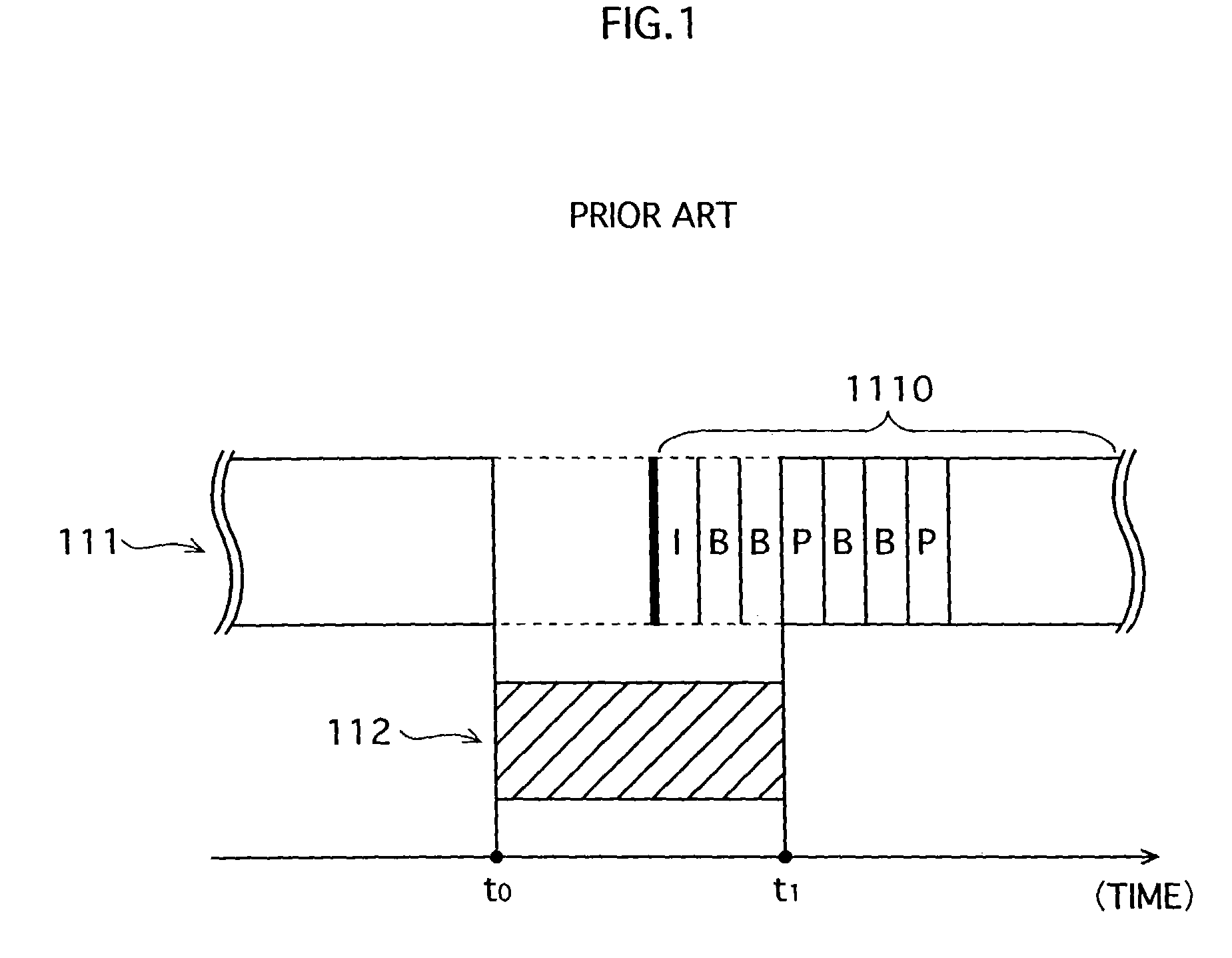
However, when transmission of broadcast video data is interrupted for a reason such as transmission of on-demand video data, the following problem arises directly after transmission of the broadcast video data resumes.
Specifically, a period of time in which video is not displayed occurs because the user terminal is unable to decode the broadcast video data transmitted directly after resuming transmission.
However, the method described in (1) requires a wider band and increases the processing load of the user terminal, while the method described in (2) increases the load in the transmission-side apparatus because the apparatus must perform extra processing to treat the user terminal that receives the on-demand video data differently from other user terminals.
This potentially leads to a problem of limiting the number of users who can be broadcast to simultaneously.

Method used


Image

  • Video data transmission/reception system in which compressed image data is transmitted from a transmission-side apparatus to a reception-side apparatus
  • Video data transmission/reception system in which compressed image data is transmitted from a transmission-side apparatus to a reception-side apparatus
  • Video data transmission/reception system in which compressed image data is transmitted from a transmission-side apparatus to a reception-side apparatus

Examples


modification example

[0132]The system 1 in the above-described embodiment enables broadcast video data to be correctly decoded when interruption / resumption of transmission of broadcast video caused by transmission of on-demand video data occurs. In contrast, the following modification example solves a problem that arises in a user terminal that is able to receive a plurality of types of broadcast video data. The problem is that when switching from one type of broadcast video data to another, the user terminal may not be able to correctly decode the broadcast video data after switching until the next GOP, depending on the type of frame of broadcast video data that is received directly after the switch.

[0133]The following describes the system of this modification example. Much of the structure of this system is the same as the system of the embodiment, and therefore the following description focuses of the differences.

[0134]In a system 9 in FIG. 10, a plurality of types of broadcast video data is provided...

modification example 2

[0146]One possible service is one in which, during transmission of particular on-demand data (first on-demand data), transmission of other on-demand data (second on-demand data) interrupts the transmission of the first on-demand data, and then transmission of the first on-demand data resumes. In this case the same problem arises directly after switching from second on-demand data to first on-demand data as in the above-described embodiment. The present modification is a system that deals with this kind of switch.

[0147]FIG. 12 shows a material selection apparatus 15A in a video data transmission / reception of the present modification. The characteristic compositional element of the present modification is an on-demand data reading unit 155A in the material selection apparatus 15A. In addition to switching on-demand video data that is output to a particular terminal, the on-demand data reading unit 155A outputs substitute I frame data before switching back to first on-demand video data...


PUM


Abstract

When transmission of on-demand video data interrupts transmission of broadcast video data from a distribution server 17 to a user terminal 18, the distribution server 17 transmits substitute I frame data to the terminal 18 after on-demand video data transmission in complete and before resuming broadcast video data transmission. The user terminal 18 decodes and displays the substitute I frame data, and then uses the decoded substitute I frame data as a reference frame to decode and display the first several frames of broadcast video data received directly after resumption of transmission.

Description

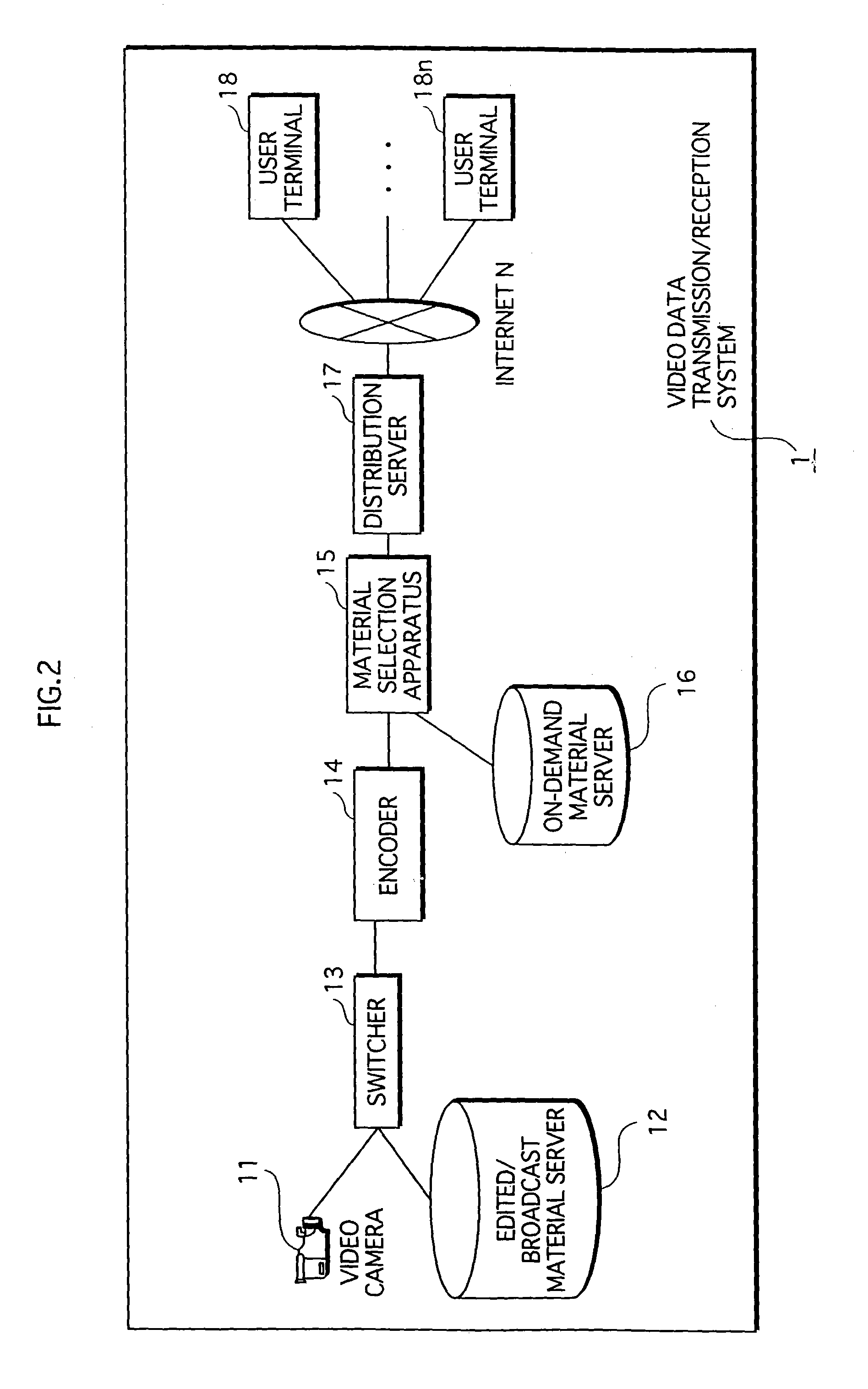
BACKGROUND OF THE INVENTION[0001](1) Field of the Invention[0002]The present invention relates a video data transmission / reception system composed of a transmission-side and a reception-side, and in which the transmission-side transmits image data that has been compressed using motion compensation interframe prediction to the reception-side, and the reception-side decodes and displays the video data.[0003](2) Related Art[0004]In recent years services that provide video data to users over the Internet are becoming common with the spread of broadband networks such as ADSL and FTTH. This video data is provided in a compressed form in order to reduce the amount of data, and one of the commonly used methods for such compression is that specified by MPEG-4. In this method, the amount of data is compressed by encoding using combinations of intraframe / interframe encoding and motion compensation prediction.[0005]One form of this kind of video data provision service is a broadcast-type servic...

Claims


Application Information

Patent Timeline
Patent Type & Authority Patents(United States)
IPC IPC(8): H04N7/173H04N7/24
CPCH04N7/17336H04N21/23424H04N21/47202H04N21/44016H04N21/2665
Inventor KURAUCHI, NOBUKAZU
Owner PANASONIC CORP
Learn More