Sound emission and collection device and sound emission and collection method

a collection device and sound emission technology, applied in the direction of electrical transducers, substation equipment, instruments, etc., can solve the problems of high processing load, inability to remove omnidirectional echoes, and inability of sound emission and collection devices to precisely select the voice of main utterers. achieve the effect of not increasing the processing load

Active Publication Date: 2014-10-07
YAMAHA CORP
View PDF19 Cites 26 Cited by
  • Summary
  • Abstract
  • Description
  • Claims
  • Application Information

AI Technical Summary

Benefits of technology

[0017]The sound emission and collection device of the invention can precisely estimate the azimuth of the sound source (for example, main utterer) without increasing processing load.

Problems solved by technology

Due to this, the sound emission and collection device cannot precisely select the voice of the main utterer when the echo sound is greater than the voice of the utterer.
However, the process of removing the echoes of all sound collection beam signals (for example, in 6 directions) causes high processing load and it is impossible to actually remove the omnidirectional echoes.

Method used


Image

  • Sound emission and collection device and sound emission and collection method
  • Sound emission and collection device and sound emission and collection method
  • Sound emission and collection device and sound emission and collection method

Examples


Embodiment Construction

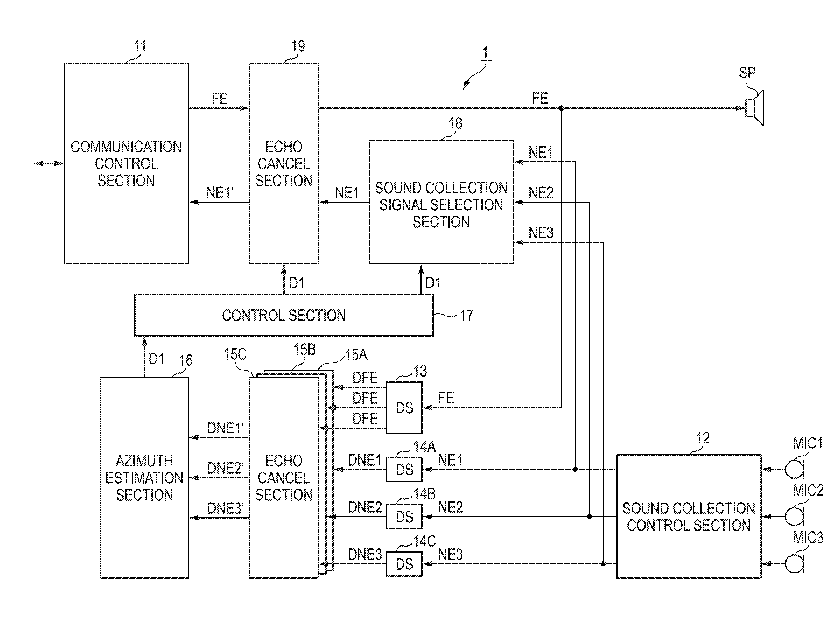
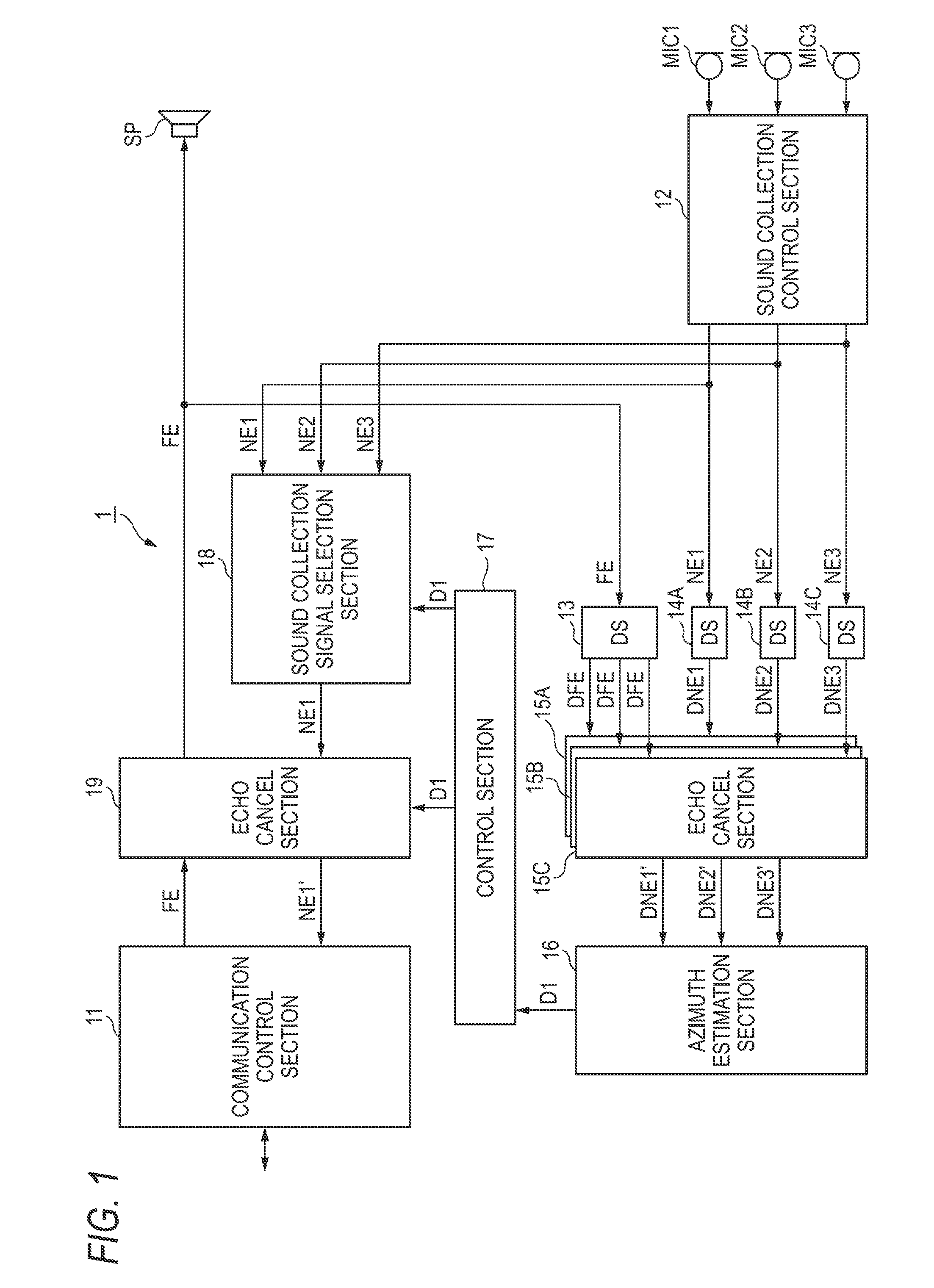
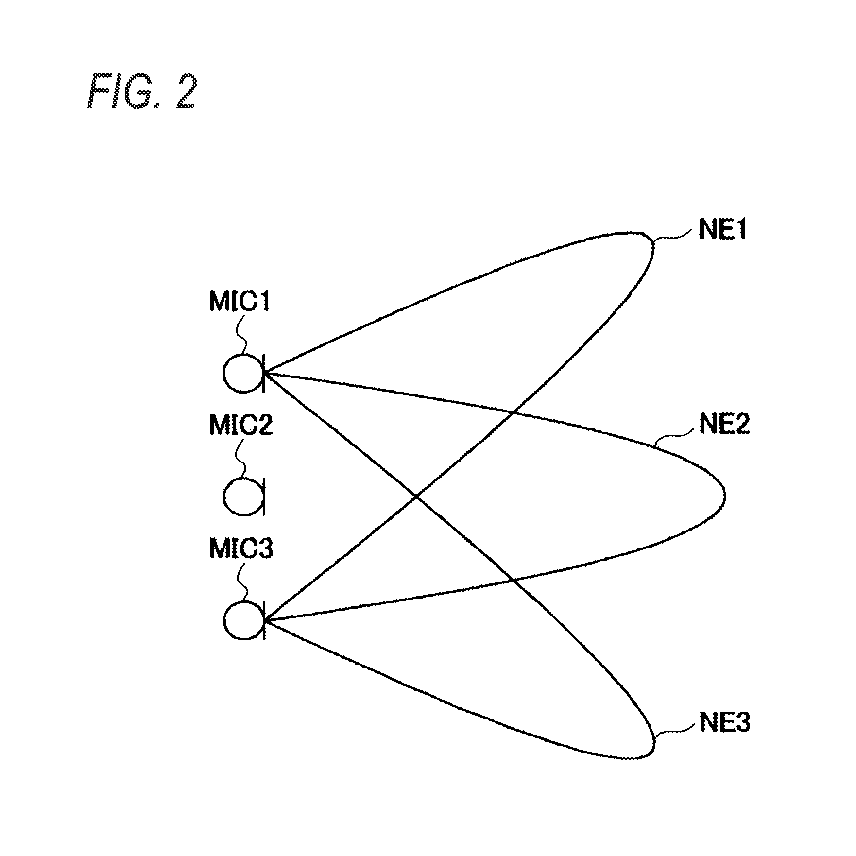
[0023]A sound emission and collection device 1 according to an embodiment of the invention will be described with reference to FIGS. 1 to 4. The sound emission and collection device 1 is connected to another sound emission and collection device via a network and the like. The sound emission and collection device 1 receives a sound signal from another sound emission and collection device, as a sound emission signal, and emits the same from a speaker SP. In addition, the sound emission and collection device 1 collects the sound at microphones MIC1 to MIC3 and produces sound collection beam signals of a plurality of azimuths. The sound emission and collection device 1 transmits a sound collection beam signal from the azimuth of a main utterer to another sound emission and collection device.

[0024]First, functions and configurations of the sound emission and collection device 1 will be described with reference to FIGS. 1 and 2. FIG. 1 is a block diagram showing functions and configuratio...


PUM


Abstract

Provided is a sound emission and collection device capable of estimating the azimuth of a sound source (such as a main utterer) precisely without any processing load. The sound emission and collection device (1) is connected with another sound emission and collection device via a network or the like. The sound emission and collection device (1) receives a sound signal from another sound emission and collection device, as a sound emission signal (FE), and emits the same from a speaker (SP). The sound emission and collection device (1) collects the sound at microphones (MIC1 to MIC3), and produces sound collection beam signals (NE1 to NE3) of different azimuths. The sound emission and collection device down-samples the individual sound collection beam signals (NE1 to NE3), and filters out the echoes of the down-sampled sound collection beam signals (DNE1 to DNE3). The sound emission and collection device selects the sound collection beam signal (DNE1′) of the highest signal level from the echo-filtered sound collection beam signals (DNE1′ to DNE3′). The sound emission and collection device filters out the echoes of a sound collection beam signal (NE1) from the sound collection azimuth (D1) of the sound collection beam signal (DNE1′), and transmits the same to another sound emission and collection device.

Description

[0001]This application is a U.S. National Phase Application of PCT International Application PCT / JP2009 / 068916 filed on Nov. 5, 2009 which is based on and claims priority from JP 2008-284030 filed Nov. 5, 2008 the contents of which are incorporated herein by reference in their entirety.TECHNICAL FIELD[0002]The present invention relates to a sound emission and collection device and a sound emission and collection method for collecting sounds of a plurality of azimuths.BACKGROUND ART[0003]Conventionally, a variety of sound emission and collection devices have been suggested which collect a voice of an utterer and emit the voice based on an input sound emission signal (for example, refer to Patent Document 1).[0004]For instance, the sound emission and collection device described in Patent Document 1 includes a microphone array consisting of a plurality of microphones, performs a delay process and the like for sound signals collected by the respective microphones, and produces a plurali...

Claims


Application Information

Patent Timeline
Patent Type & Authority Patents(United States)
IPC IPC(8): H04B3/20G10L21/0208G10L21/0216G10L21/0232G10L21/0272H04M1/60H04M9/08
CPCH04M9/082G10L2021/02166H04M1/6008G10L2021/02082
Inventor TANAKA, RYOKURIYAMA, NAOTO
Owner YAMAHA CORP
Why Eureka
Try Eureka