Envelope-based amplitude mapping for cochlear implant stimulus
a cochlear implant and stimulus technology, applied in the field of cochlear prosthesis, can solve the problems of increasing power consumption, computational intensive log function, and increasing power consumption, and achieve the effects of reducing the number of samples processed, computational intensive log function, and increasing the workload of speech processors
- Summary
- Abstract
- Description
- Claims
- Application Information
AI Technical Summary
Benefits of technology
Problems solved by technology
Method used
Image
Examples
first embodiment
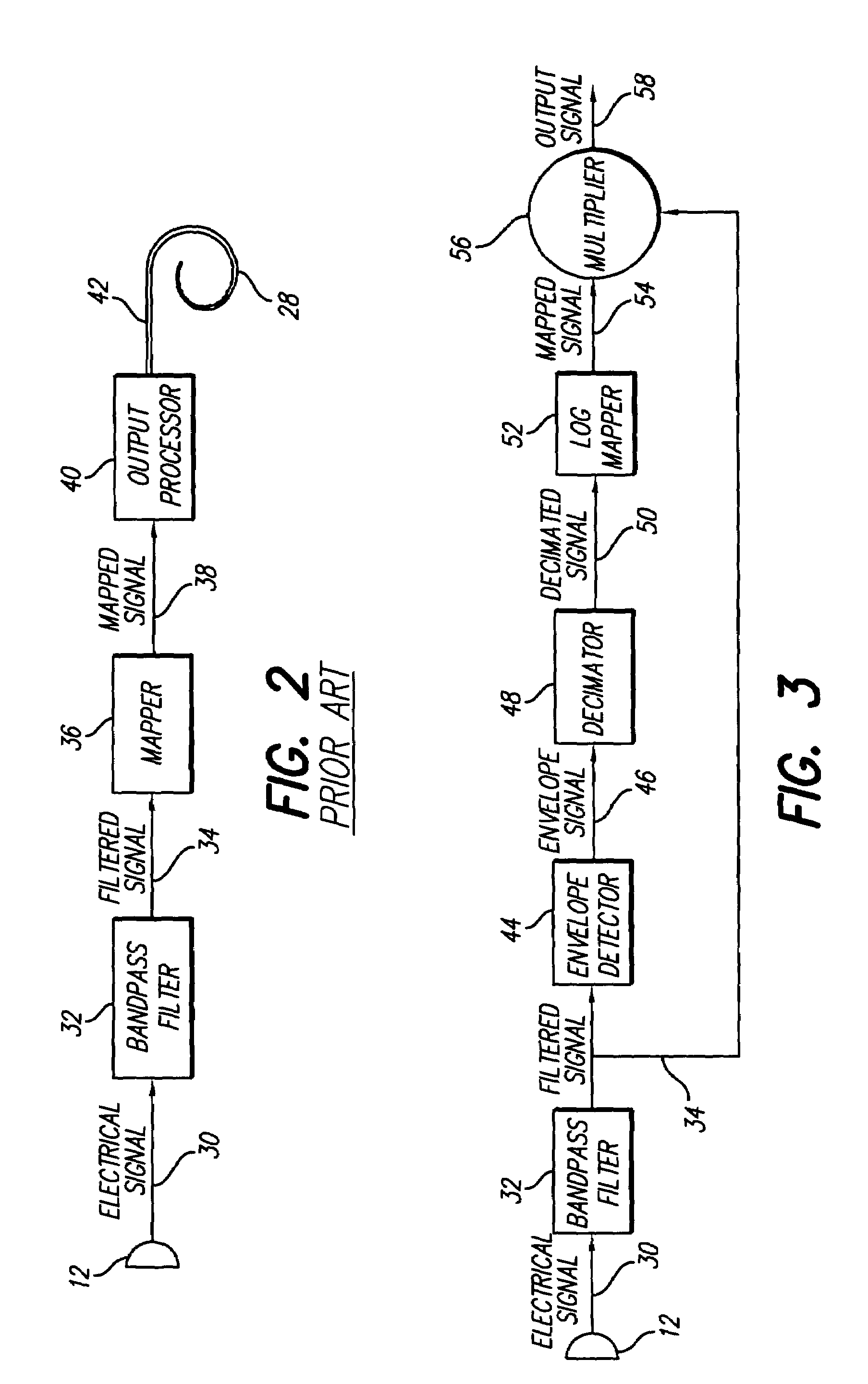
[0028]the present invention, depicted by one channel of an envelope based amplitude mapping applied to Simultaneous Analog Stimulation (SAS), is shown in FIG. 3. In practice, there are from 4 to 30 such parallel channels operating in different frequency bands. The processing up to and including the bandpass filter 32 is unchanged from known systems. The sample rate for the filtered signal 34 is between 10 KHz and 25 KHz and is preferably 13 KHz or 17 KHz. Identical filtered signals 34 produced by the bandpass filter 32 are carried on two paths. The top paths in FIG. 3 represents the heart of the envelope based amplitude mapping. An envelope detector 44 computes an envelop signal 46 from the filtered signal 34. In a preferred embodiment the envelope detector 44 is a full wave rectifier followed by a lowpass filter with a cutoff of 100 Hz. The particular envelope detector 44 that is best for a specific ICS system depends on the details of processing that precedes the envelope detector...
third embodiment
[0035]A third embodiment comprising a second application of the present invention to CIS amplitude mapping is shown in FIG. 5. The microphone 12 and bandpass filter 32 are the same as in FIGS. 2, 3, and 4. The filtered signal 34 is processed by two parallel paths in the second CIS embodiment. A fourth envelope detector 84 to produce a fourth envelope signal 86, and the envelope signal 86 is processed by a fourth decimator 88, to generate a fourth decimated signal 90. A preferred envelope detector 84 comprises a half wave rectifier and a low pass filter. The lowpass filter has a cut off frequency of about 800 Hz to 2000 Hz, preferably 800 Hz. While the envelope detector and decimator are shown as separate processing steps, in a preferred implementation, the lowpass filter and decimator are combined into a single Finite Impulse Response (FIR) filter.
[0036]Continuing with FIG. 5, the filtered signal 34 is processed by a fifth envelope detector 92 to obtain a fifth envelope signal 94, a...
PUM
 Abstract
Description
Claims
Application Information
 - R&D
- Intellectual Property
- Life Sciences
- Materials
- Tech Scout
- Unparalleled Data Quality
- Higher Quality Content
- 60% Fewer Hallucinations
Browse by: Latest US Patents, China's latest patents, Technical Efficacy Thesaurus, Application Domain, Technology Topic, Popular Technical Reports.
© 2025 PatSnap. All rights reserved.Legal|Privacy policy|Modern Slavery Act Transparency Statement|Sitemap|About US| Contact US: help@patsnap.com


