Surface discharge type plasma display screen with dual discharge spaces

A technology of discharge space and plasma, applied in static indicators, cold cathode tubes, instruments, etc., can solve the problems that non-discharge gaps cannot be guaranteed, phosphors are not fully utilized, and PDP life is affected.

Inactive Publication Date: 2002-11-27
XI AN JIAOTONG UNIV
View PDF0 Cites 6 Cited by
  • Summary
  • Abstract
  • Description
  • Claims
  • Application Information

AI Technical Summary

Problems solved by technology

[0005] 1. In order to prevent optical crosstalk, some areas of the discharge electrodes on the upper substrate do not participate in the discharge, which reduces the space utilization of the discharge surface and is not conducive to the improvement of brightness
[0006] 2. The fluorescent powder in the non-discharge area that does not participate in the discharge is not fully utilized due to the small ultraviolet radiation generated by the discharge.
On the contrary, the phosphor under the discharge area has been bombarded by ions and photons, and the deterioration is serious, which affects the life of the PDP
[0007] 3. Since there is always a part of the space that does not participate in the discharge, the improvement of resolution is limited
This connection method cannot guarantee that the non-discharge gap will not discharge, which is not conducive to improving the contrast

Method used


Image

  • Surface discharge type plasma display screen with dual discharge spaces
  • Surface discharge type plasma display screen with dual discharge spaces
  • Surface discharge type plasma display screen with dual discharge spaces

Examples


no. 1 example

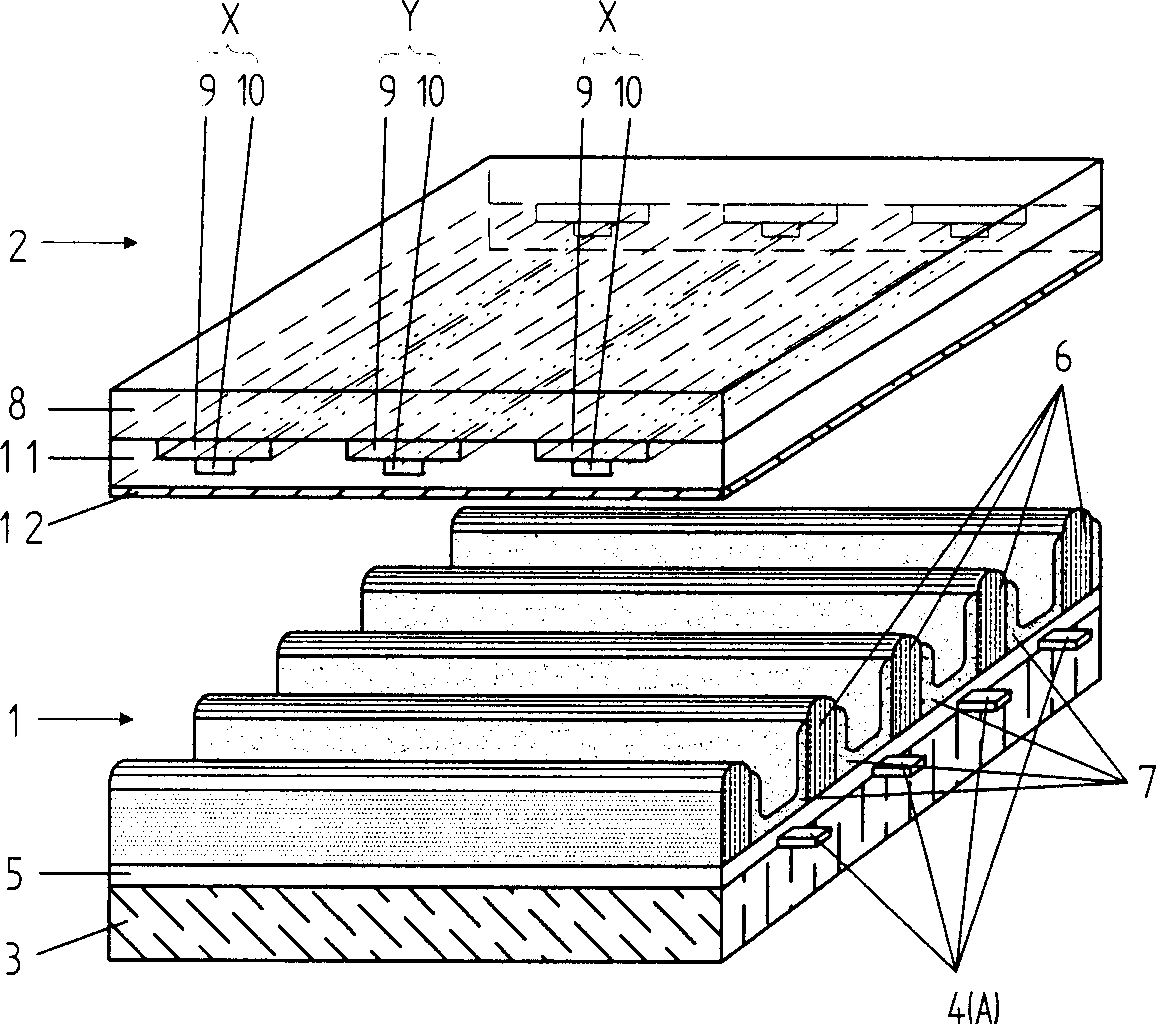
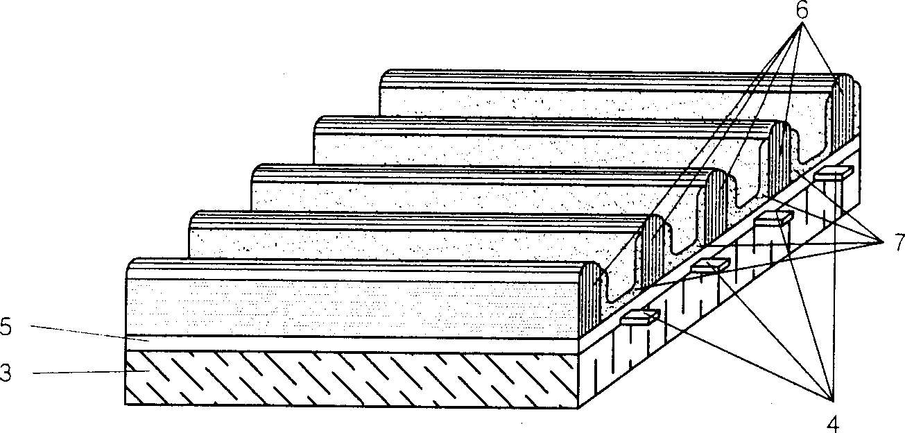
[0047] Please refer to figure 1 , Figure 5 and Image 6 As shown, the plasma display screen of the present invention includes a lower substrate 1, an upper substrate 2 and a control and driving circuit. Wherein: the lower substrate 1 is composed of a lower substrate glass 3, a metal electrode 4 formed on the lower substrate glass 3, a dielectric layer 5 formed on the metal electrode 4, and a dielectric layer 5 formed on the dielectric layer 5 to prevent optical crosstalk The barrier ribs 6 and the red, green and blue photophosphor 7 formed between the barrier ribs 6 are formed. The upper substrate 2 includes an upper substrate glass 8 , transparent electrodes 9 formed on the lower surface of the upper substrate glass 8 at equal intervals, a metal bus electrode 10 formed at the center of the lower surface of the transparent electrode 9 , and the metal bus electrode 10 consists of a dielectric layer 11 and a protective film 12 formed on the lower surface. The address electr...

no. 4 example

[0051] image 3 As shown, in the first embodiment, a fourth embodiment of the present invention is constituted by coating all monochromatic photo-phosphor powders between the barriers to realize monochromatic display. Fifth embodiment:

[0052] Figure 4 As shown, in the first embodiment, the barrier is not coated with fluorescent powder but only filled with discharge gas, and the color of the gas discharge is used to realize monochrome display, which constitutes the fifth embodiment of the present invention. Sixth embodiment:

[0053] Figure 7 , Figure 8 As shown, in the above-mentioned first to fifth embodiments, the scan electrodes and the sustain electrodes are made of unequal widths, including the unequal widths of the transparent electrodes and the unequal widths of the metal bus electrodes, but the width of the transparent electrodes on the scan electrodes All are the same, the widths of the metal bus electrodes are all the same, the widths of the transparent ele...


PUM


Abstract

An AC surface discharge type plasma display screen with dual discharge spaces is composed of upper and lower base plates. The scanning electrodes and maintaining electrodes on upper base plate are parallelly and alternately arranged. A discharge unit is formed by a scanning electrode, its adjacent two maintaining electrodes and an addressing electrode on the lower base plate. An image frame is displayed by two fields so as to realize the whole screen under the discharged zone in the display process of one frame. Its advantages are high luminous efficient and brightness, low cost of driver, and long service life.

Description

1. Technical field [0001] The invention relates to an AC surface discharge type plasma display screen with double discharge spaces. 2. Background technology [0002] Existing conventional AC surface discharge plasma display screens include three-electrode structure, four-electrode structure and five-electrode structure. In these structures, the structures of the lower substrate are all the same or similar, and the lower substrate includes a lower substrate glass, parallel address electrodes formed on the lower substrate glass, and a lower substrate glass plate provided with the parallel address electrodes. A dielectric layer formed on the dielectric layer, a barrier rib parallel to the address electrodes formed on the dielectric layer for separating adjacent discharge spaces and maintaining the height of the discharge space, and a photochromic coating is applied between the adjacent barrier ribs Phosphor powder; the upper substrate includes an upper substrate glass, a scan ...

Claims


Application Information

Patent Timeline
Patent Type & Authority Applications(China)
Inventor 卜忍安张军沈思宽
Owner XI AN JIAOTONG UNIV
Why Eureka
Try Eureka